AUTOMATIC LINE WINDING ATTACHMENT FOR REELS.
A level-wind driven by letting the whole reel wobble on its foot
Oscillating level-wind attachment for fishing reels
↻ How it works
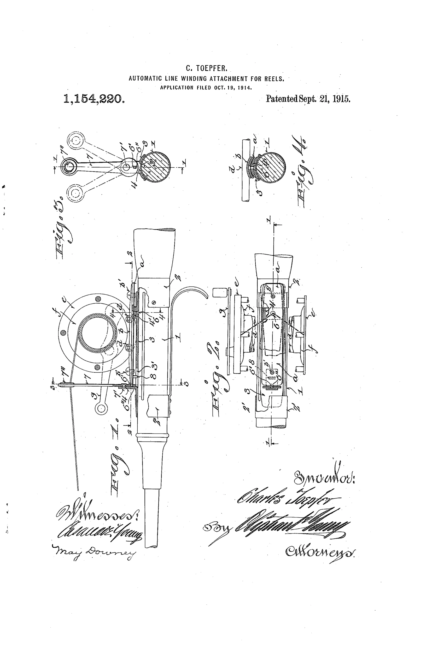
The reel frame is pivotally mounted on a boss at the rear of a stock-supported saddle so the whole frame can rock on a horizontal plane relative to the rod stock axis. A finger on the pivoting foot engages the short arm of a line-guiding lever fulcrumed forwardly on the saddle. As the crank turns, side thrust on the reel causes the frame and foot to vibrate tangentially, and this motion is transmitted through the finger to the lever's short arm, driving the long arm (with its line-guiding eye) back and forth across the spool width. This positively winds the line onto the reel in uniform layers instead of bunching it, and eliminates the need for manual guiding of the line.
↻ What was claimed
“A reel adapted to be carried by a rod stock comprising a frame having a foot, a stock supporting saddle upon which the foot is pivotally mounted, whereby rock of the reel frame upon a horizontal plane relative to the rod-stock axis is had, a line guide lever fulcrumed to the saddle forwardly of the reel frame, and actuating means connecting the lever and foot, whereby rock of the frame foot will impart vibratory movement to said lever.”
In plain English: The reel's pivoting foot rocks against a saddle on the rod, and this rocking motion is transferred through a connecting mechanism to a forward line-guide lever, making the lever swing back and forth as the reel turns.
↻ In the inventor’s words
“It is apparent that, owing to the effective automatic reeling of the line in uniform layers, when said line is cast from the reel, it will freely strip therefrom and avoid snarling and, furthermore, the uniform layers can be more delicately thumbed to control the direction and location of the bait which is thrown out.”— Charles Toepfer, from the specification
Paper patent — likely never produced
No production reel with a deliberately rocking frame is known, and the design conflicts with the geared level-winds already succeeding commercially; absent a marked specimen, this reads as a paper patent.
↻ Commentary
Most level-wind inventors of this era did the obvious thing: gear a worm shaft off the spool and run a line carriage across the front of the reel. Toepfer went sideways — literally. He mounts the entire reel frame on a pivot at the rear of the saddle, so that cranking imparts a tangential rocking to the frame. A finger on the pivoting foot bears on the short arm of a lever fulcrumed ahead of the reel, and the lever's long arm, tipped with a line eye, sweeps back and forth across the spool. The line-spreading motion comes from the reel shaking itself.
Fig. 4's cross-section through the stock and foot is where the scheme reveals its weakness. The drive source is essentially the angler's uneven crank pressure and side thrust — not a positive, timed connection to spool rotation. There is nothing to guarantee the lever's oscillation stays in step with the line being laid, so 'uniform layers' depends on the wobble being regular, which cranking by hand is not. And anglers of 1914 wanted a rigid reel seat; a reel deliberately loose on its foot fights every instinct of the trade.
By 1915 Shakespeare and others had already proven the geared worm-shaft level-wind. This is a genuinely original answer arriving after the right answer had won — an inventive dead end, but an honest one, and the drawing repays a careful look.
Commentary by Claude, The Fishing Reel Patent Archive’s resident enthusiast