The Fishing Reel Patent Archive

The mechanical heart of American angling

All 139 patents

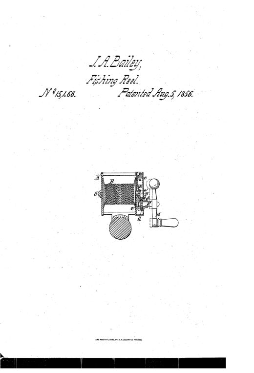
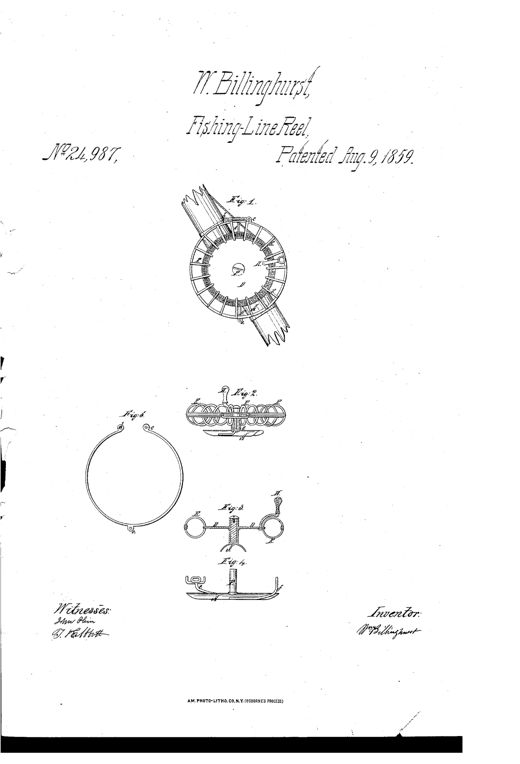
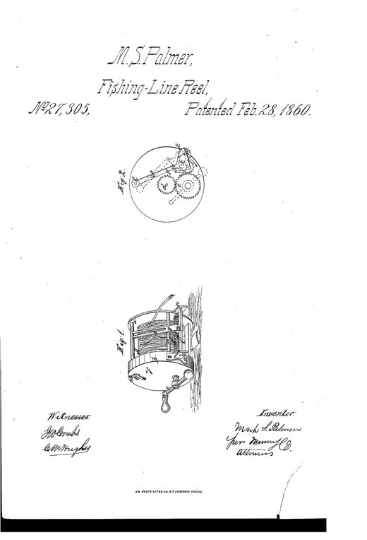
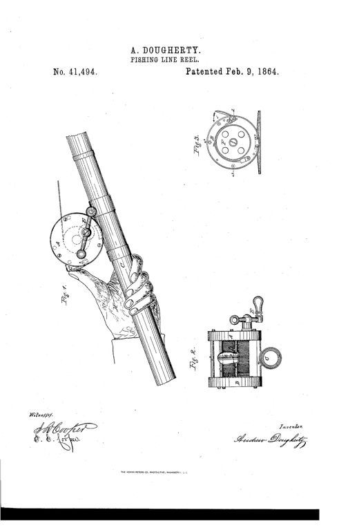
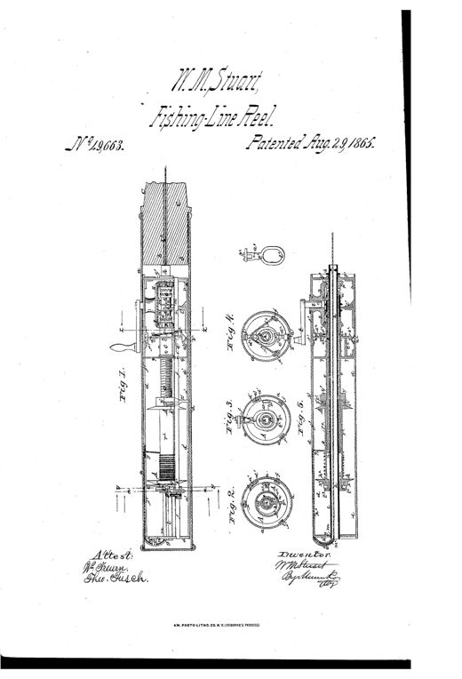
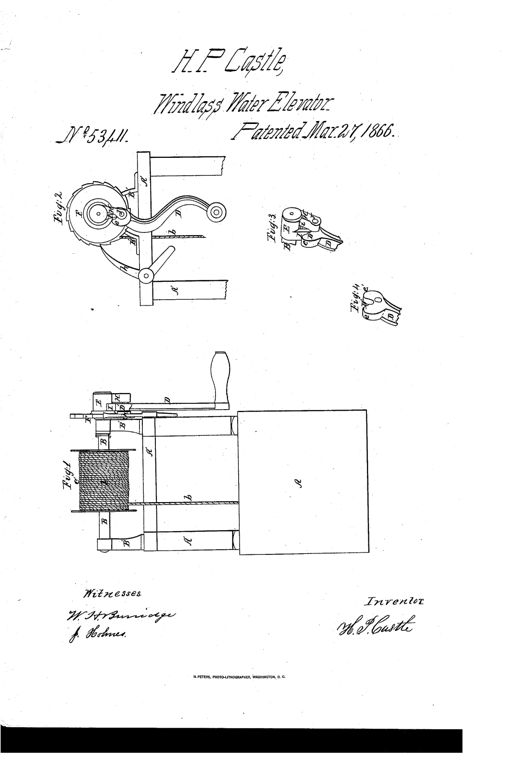
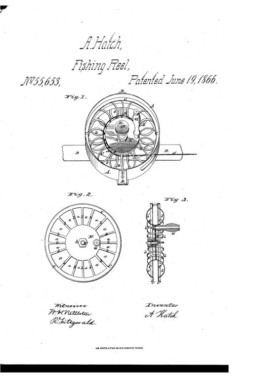
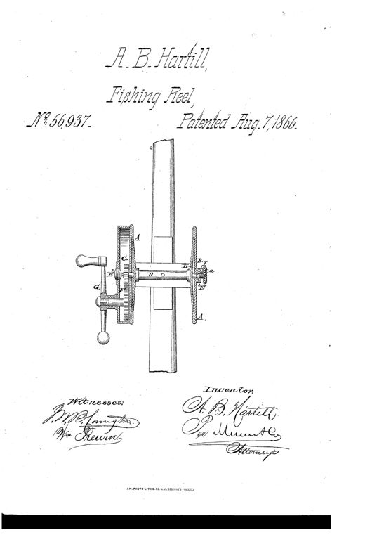
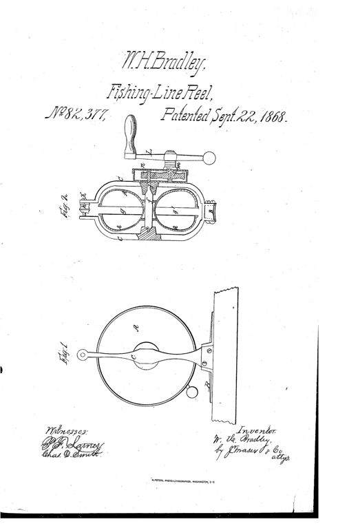
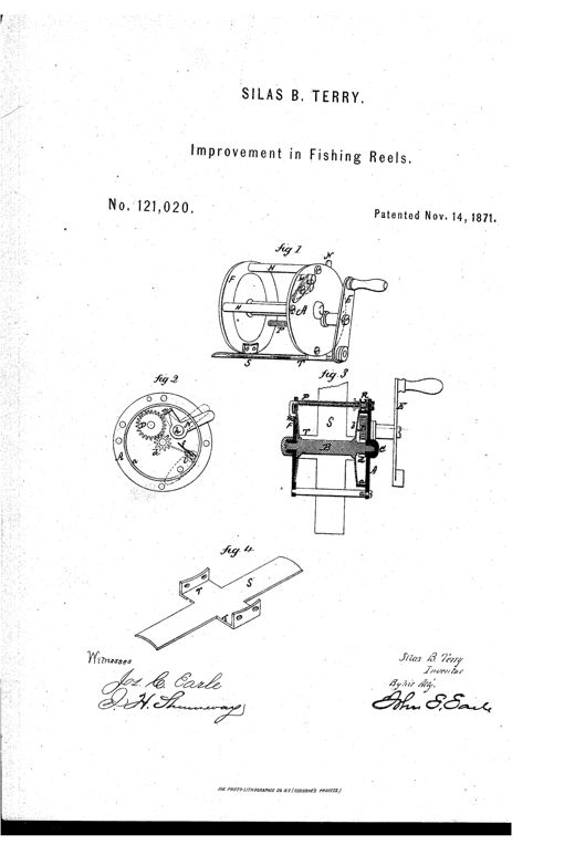
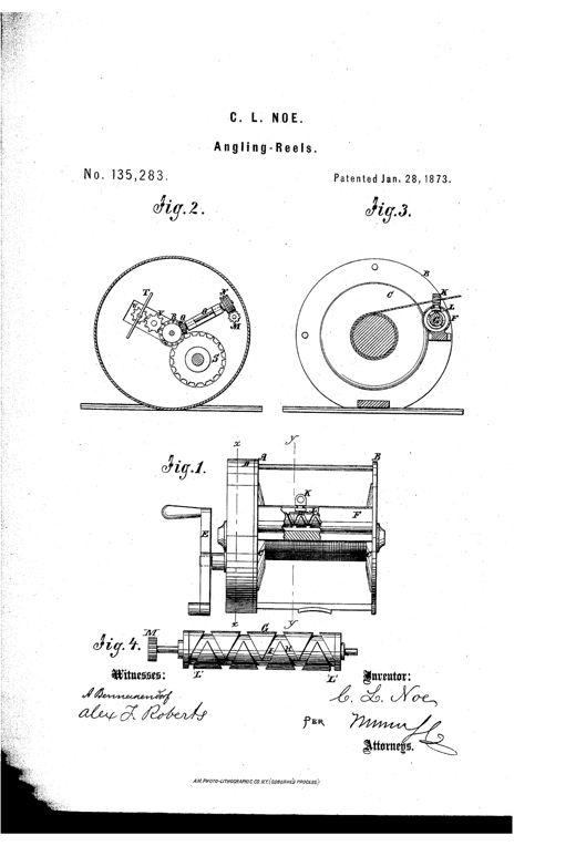
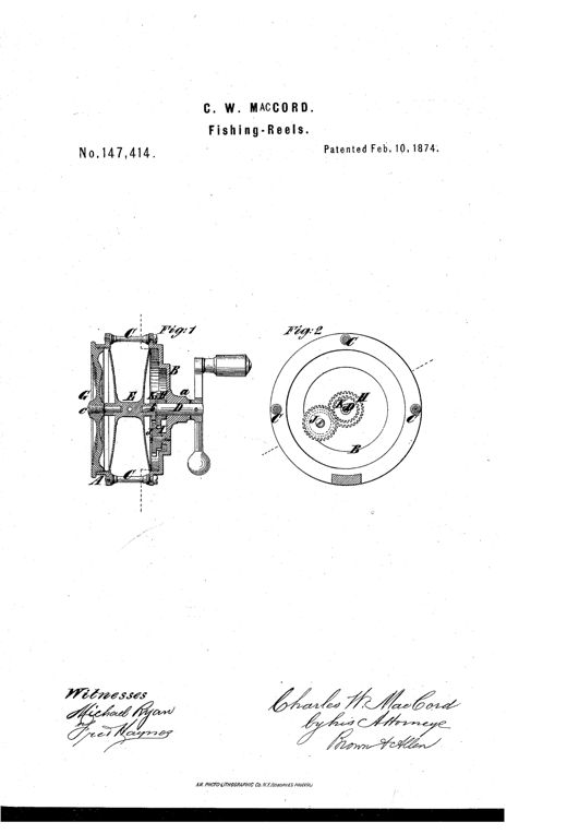
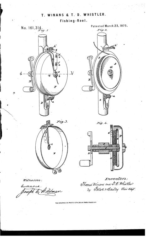
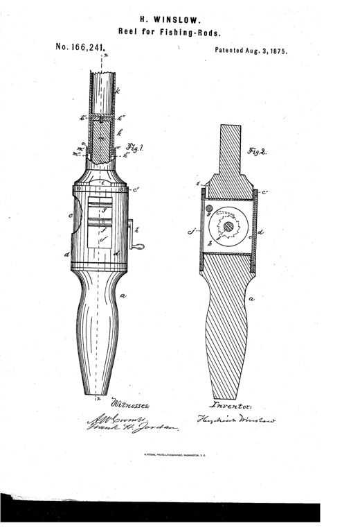
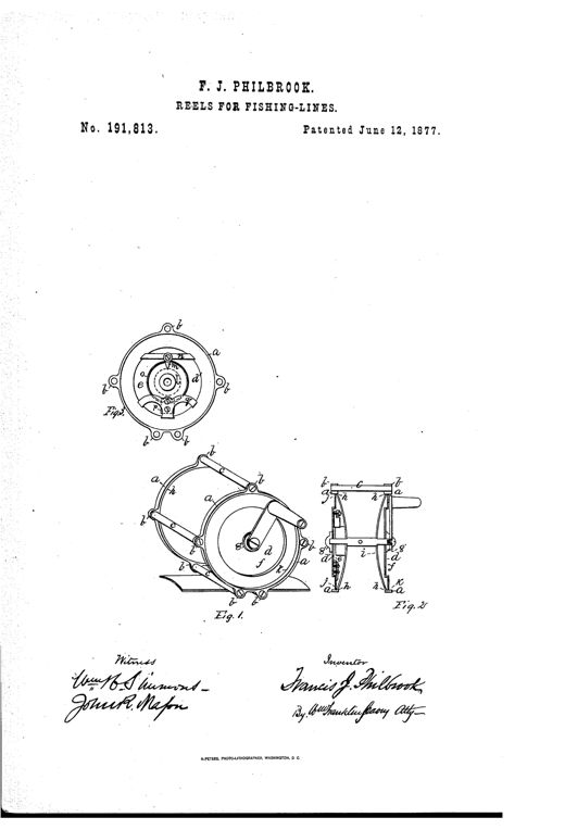
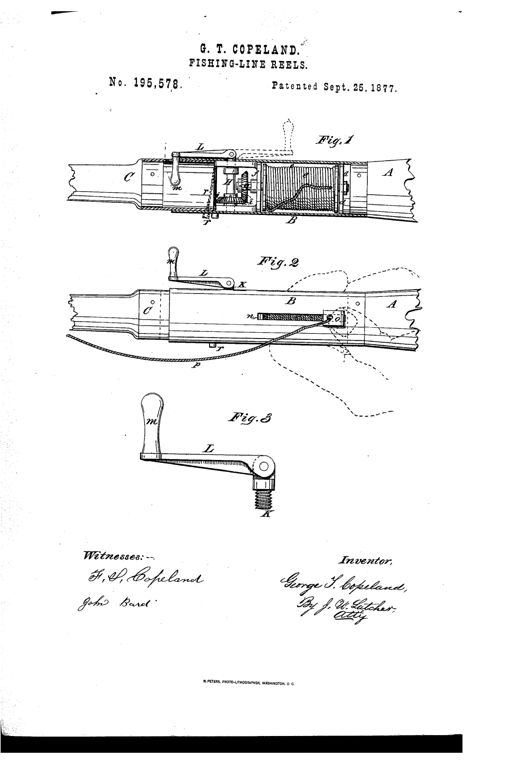
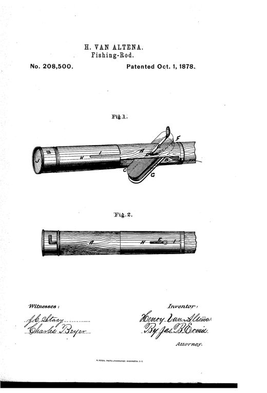
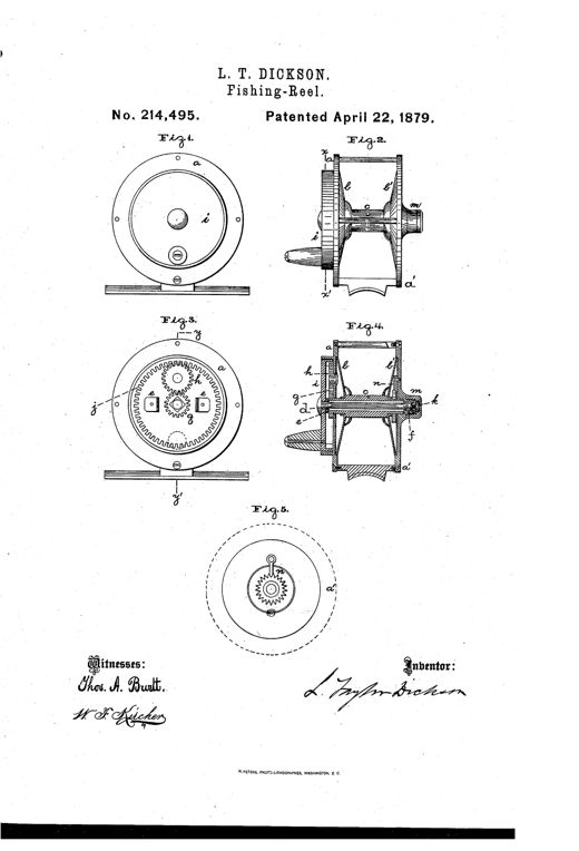
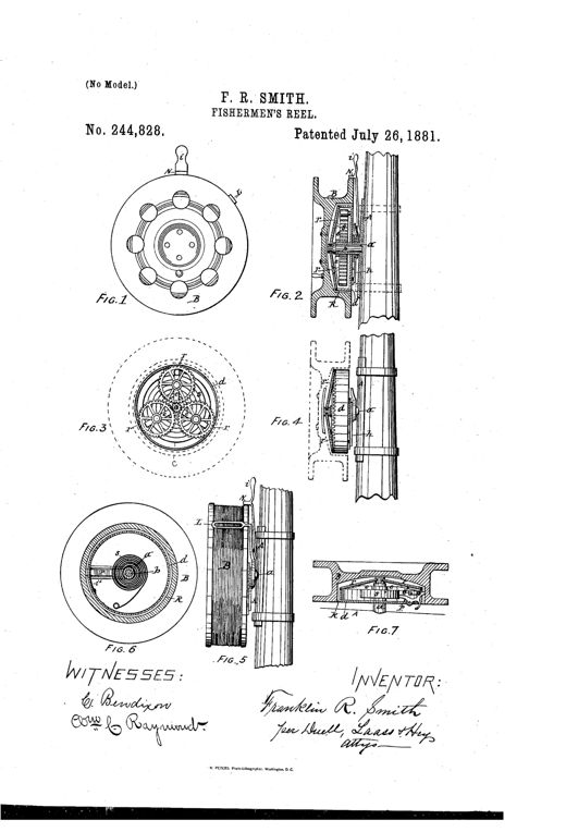
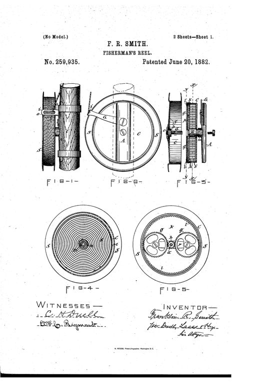
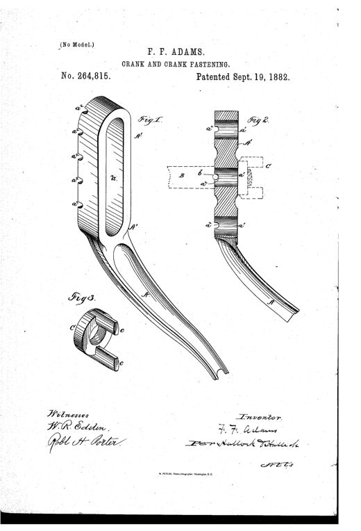
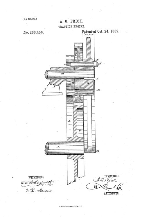
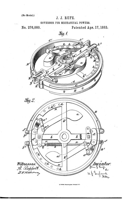
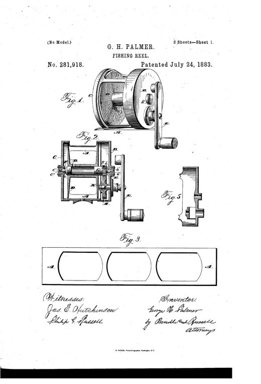
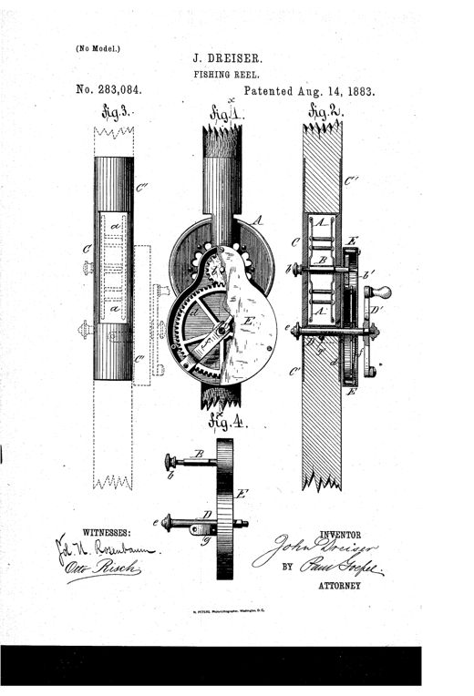
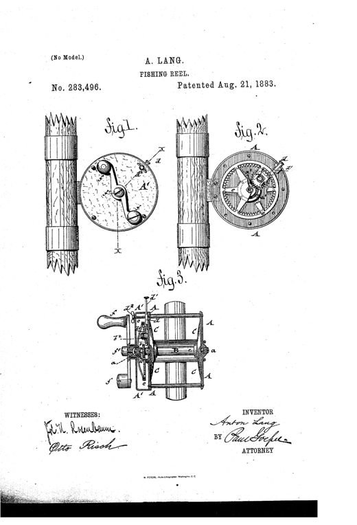
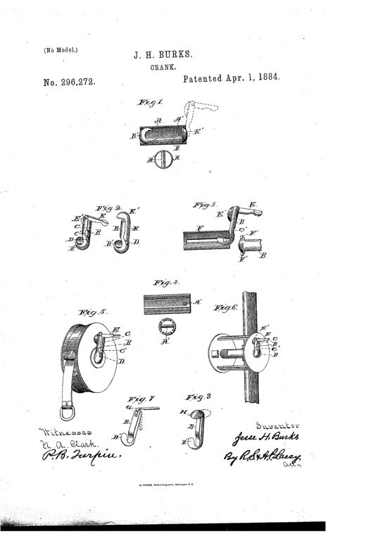
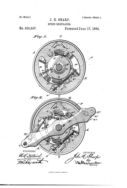
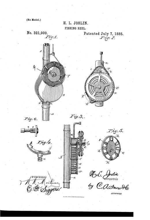
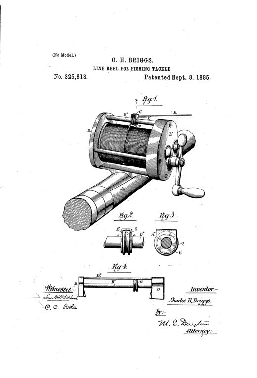
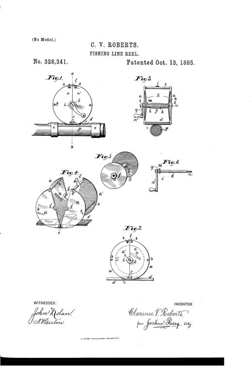
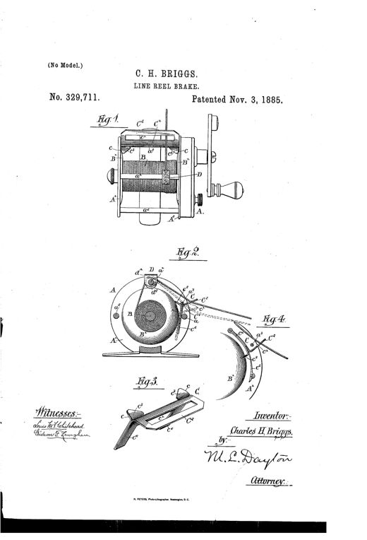
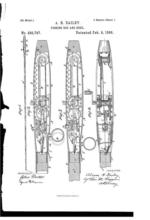
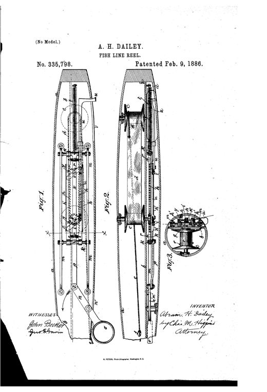
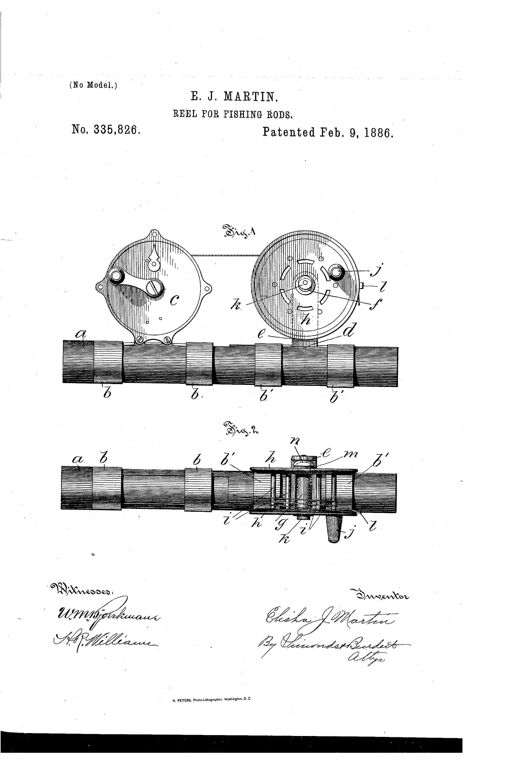
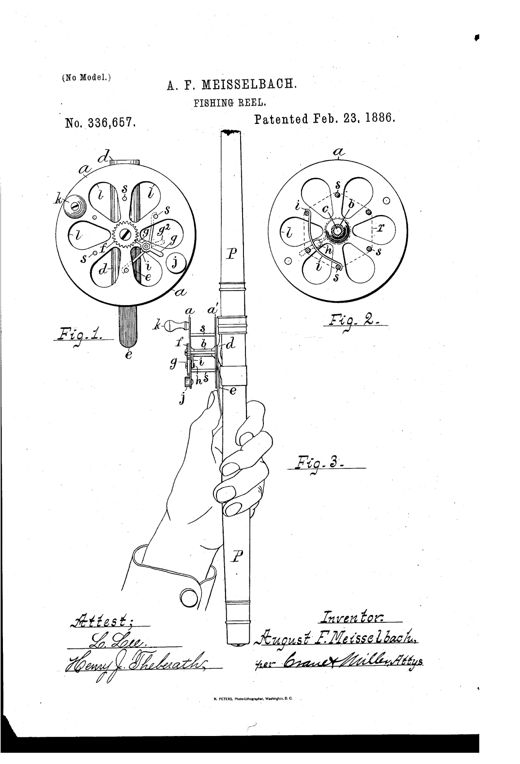
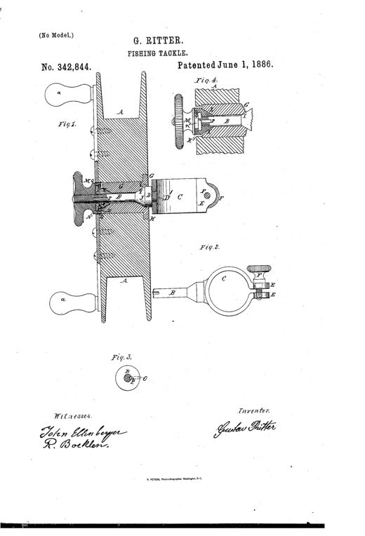
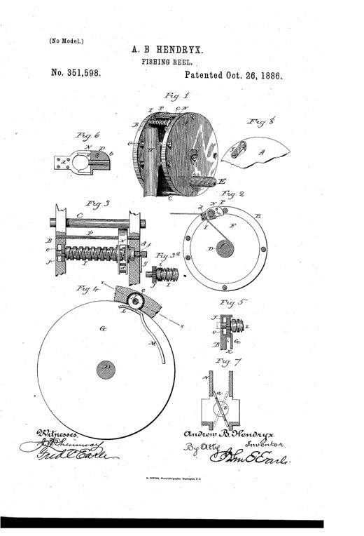
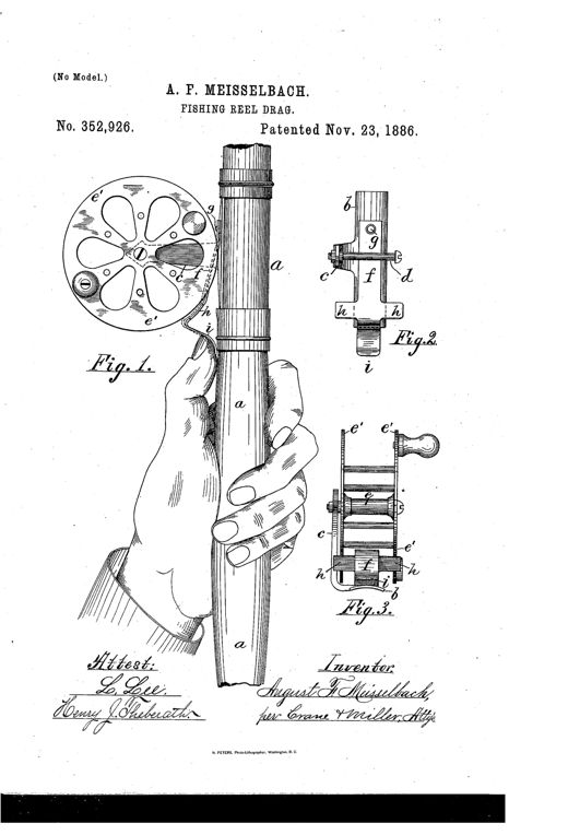
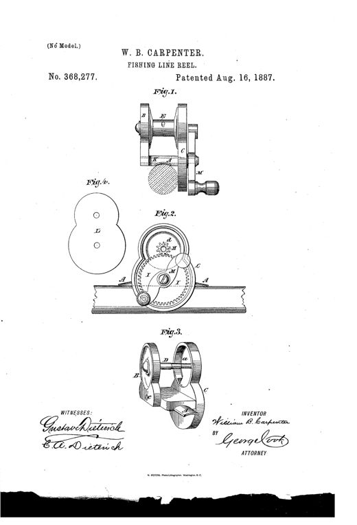
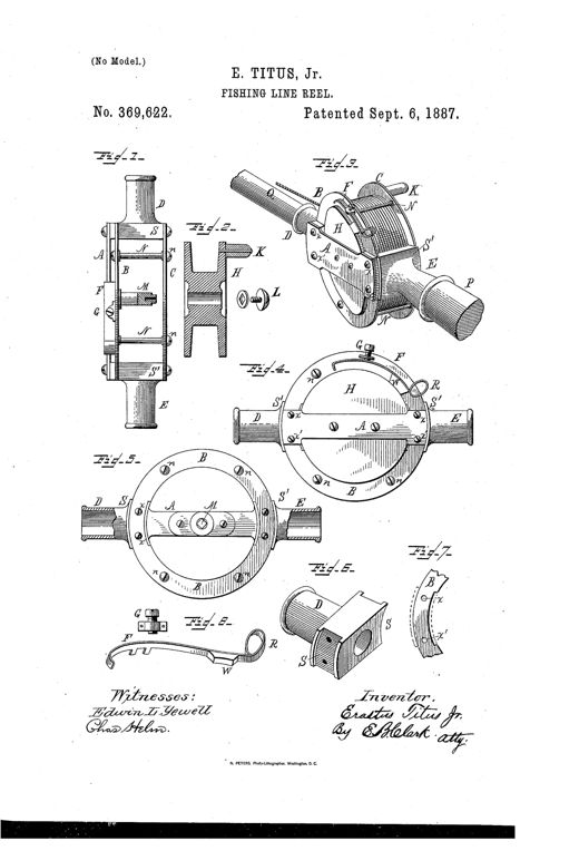
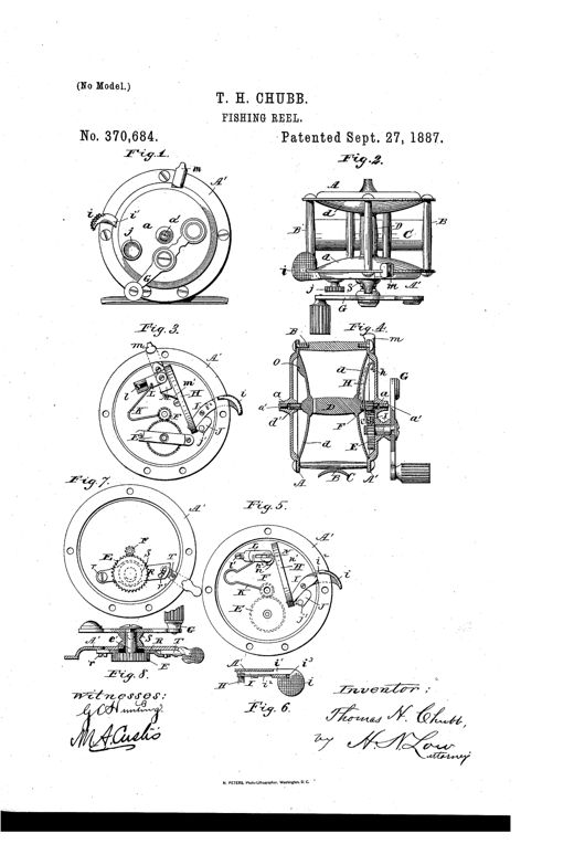
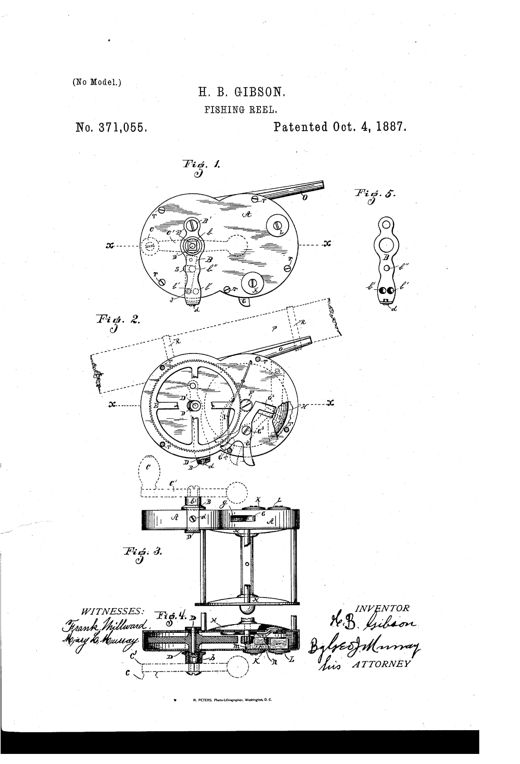
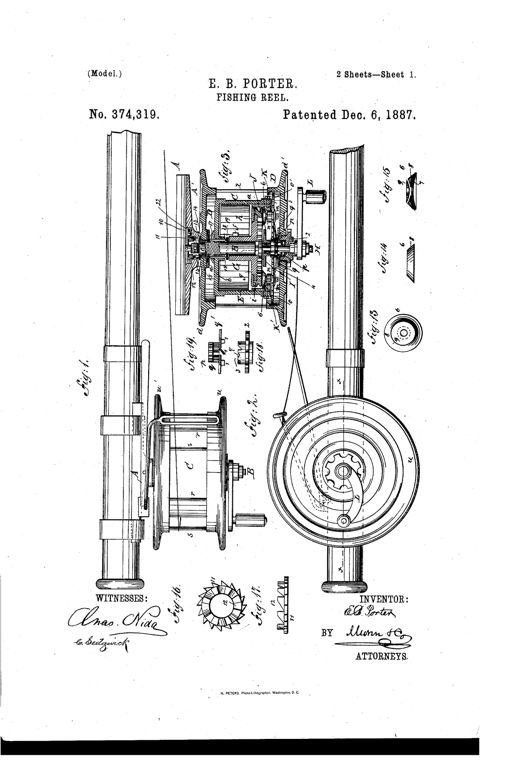
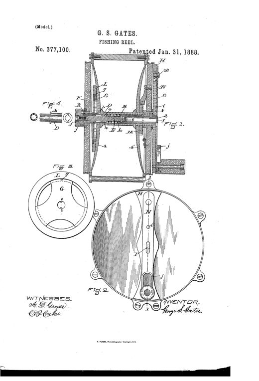
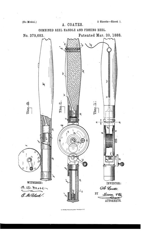
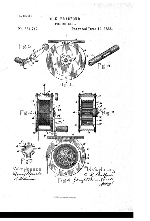
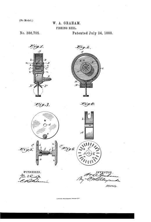
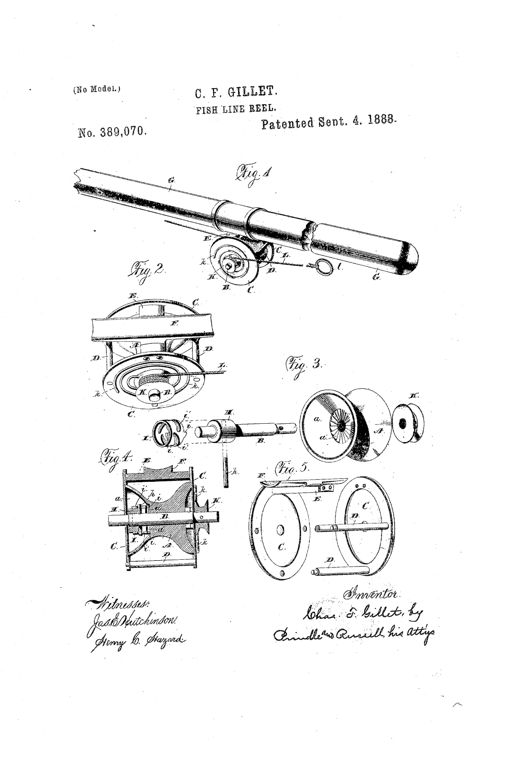
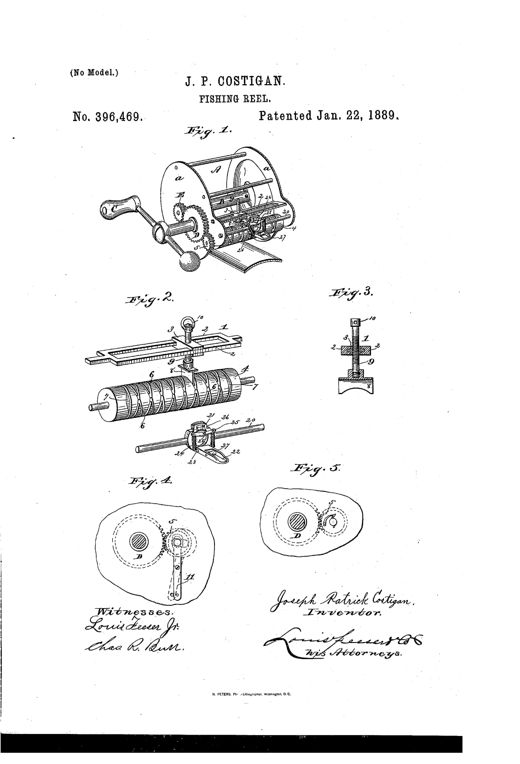
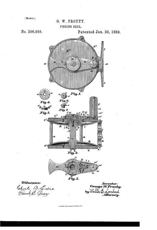
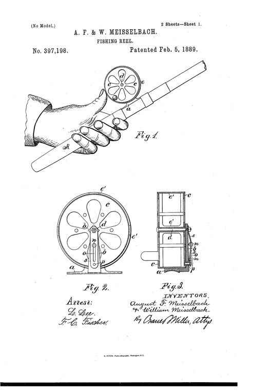
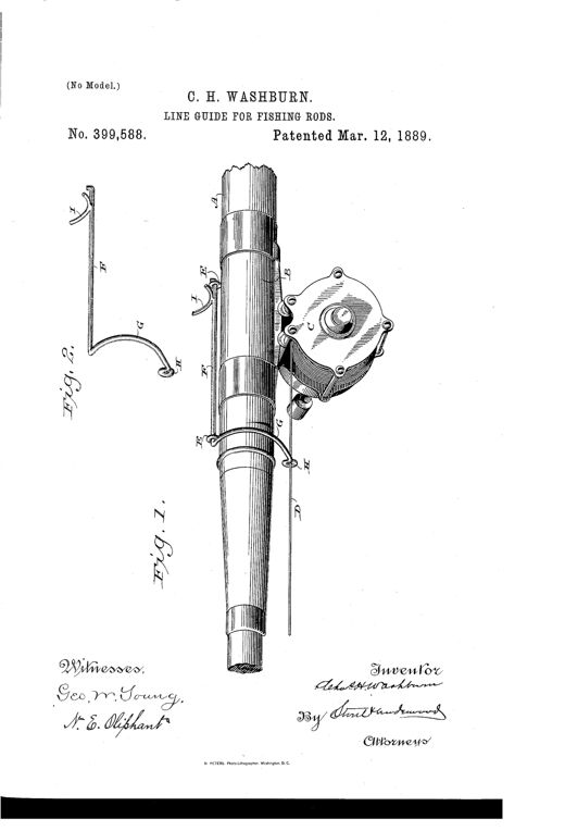
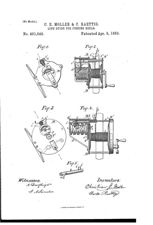
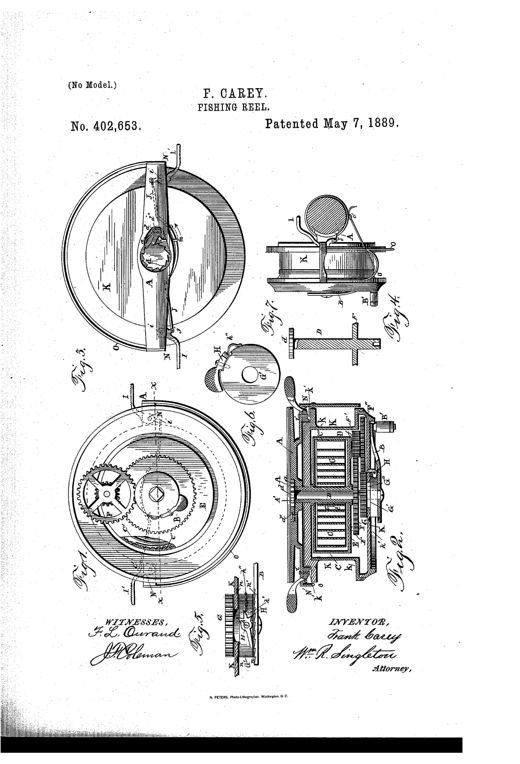
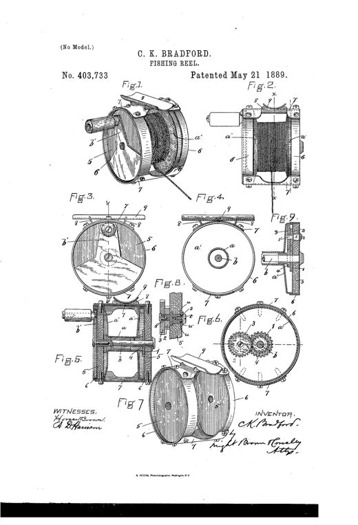
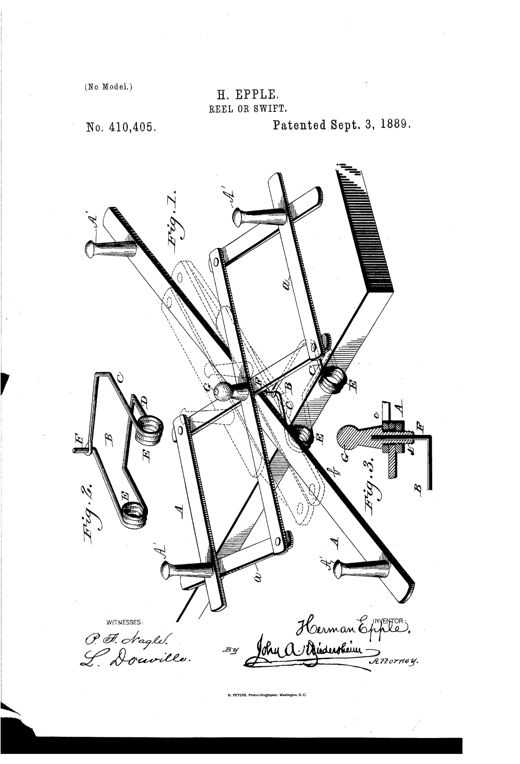
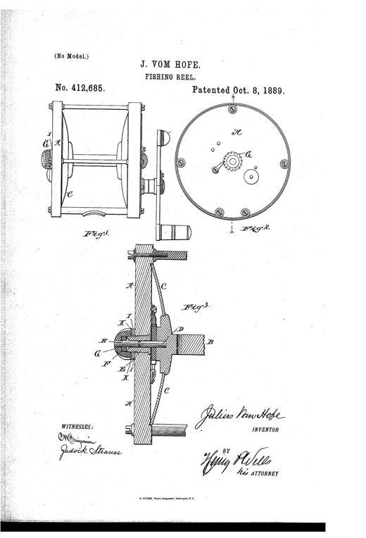
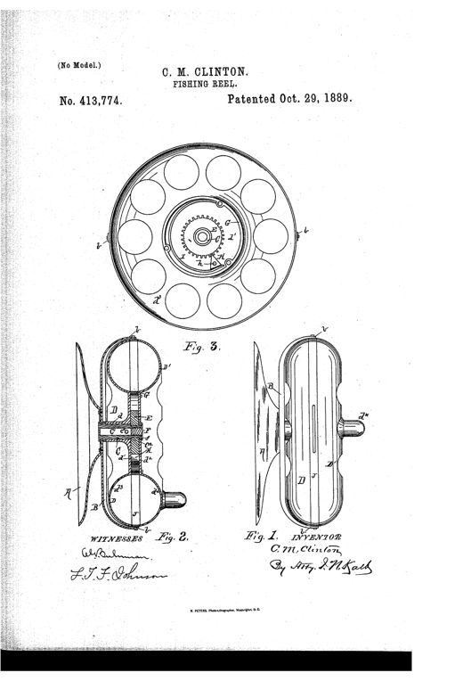
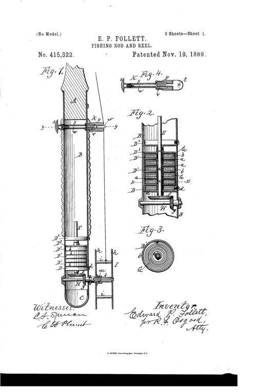
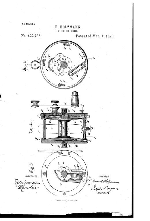
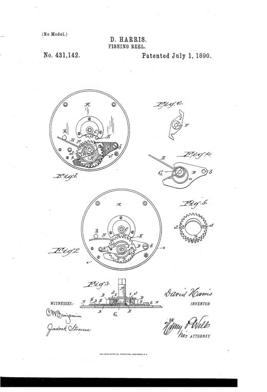
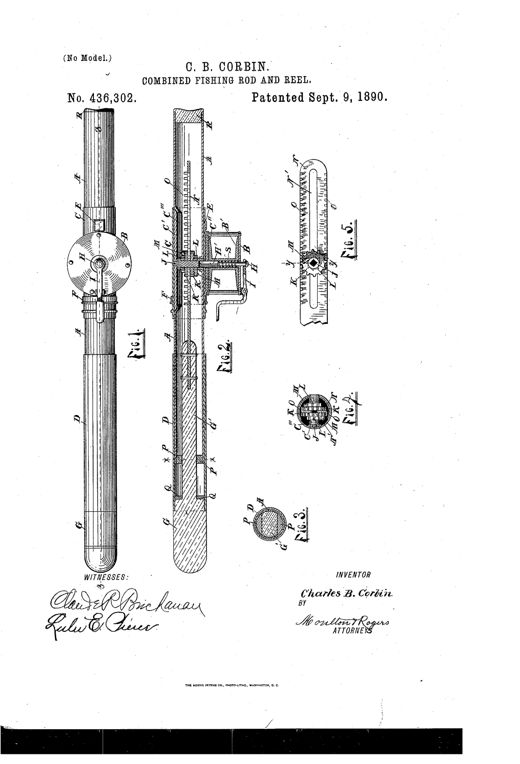
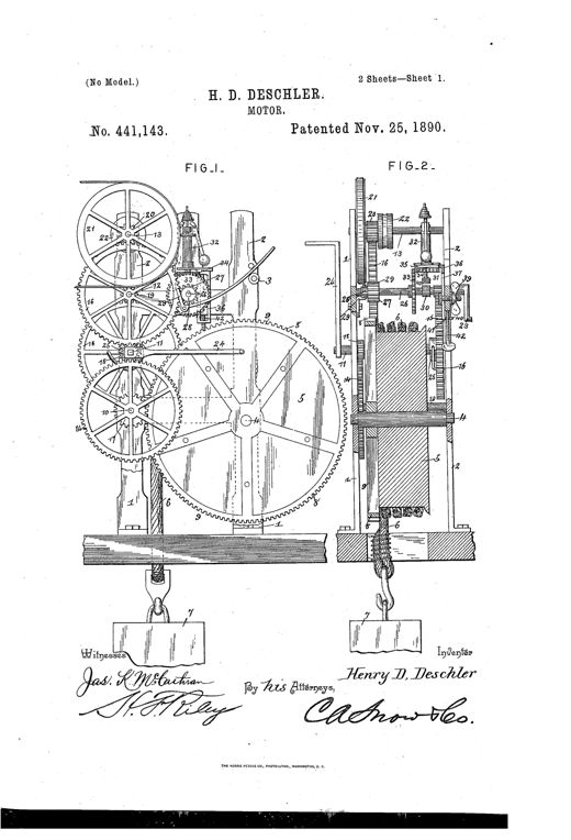
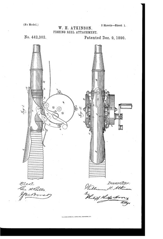
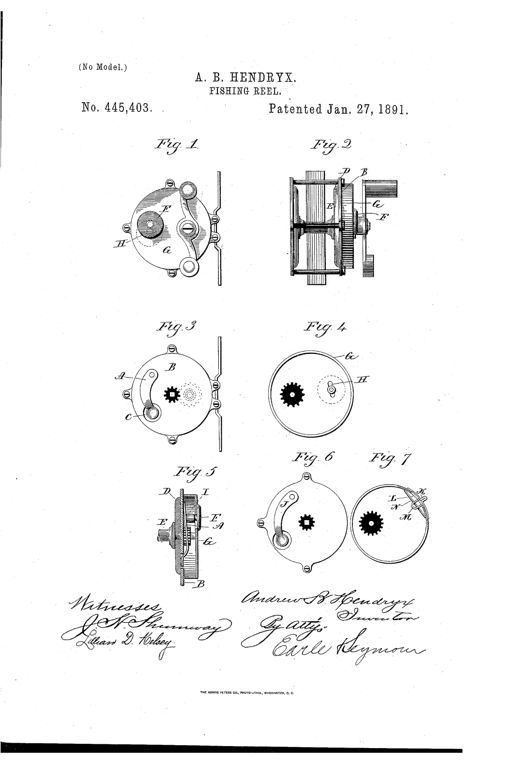
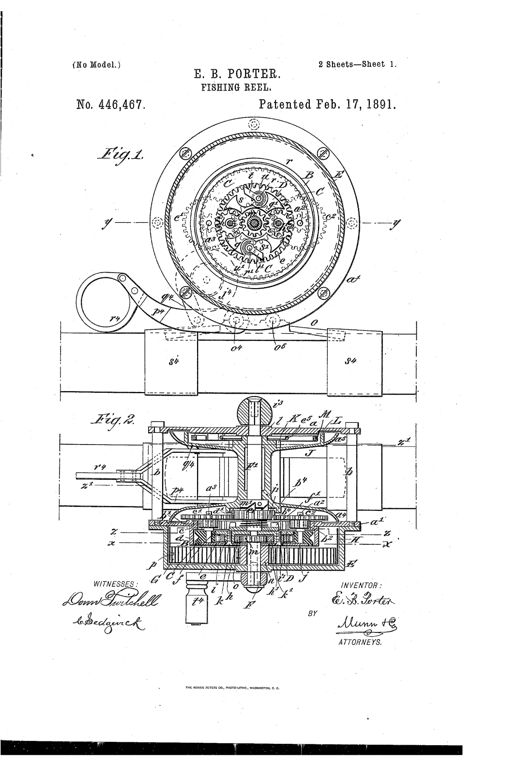
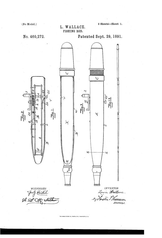
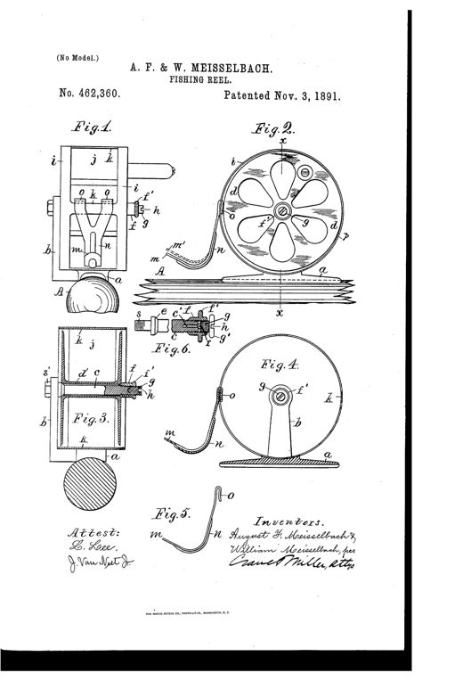
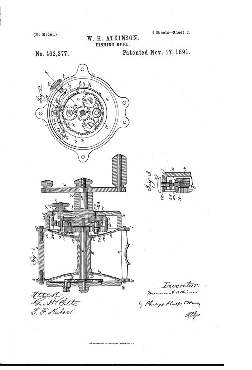
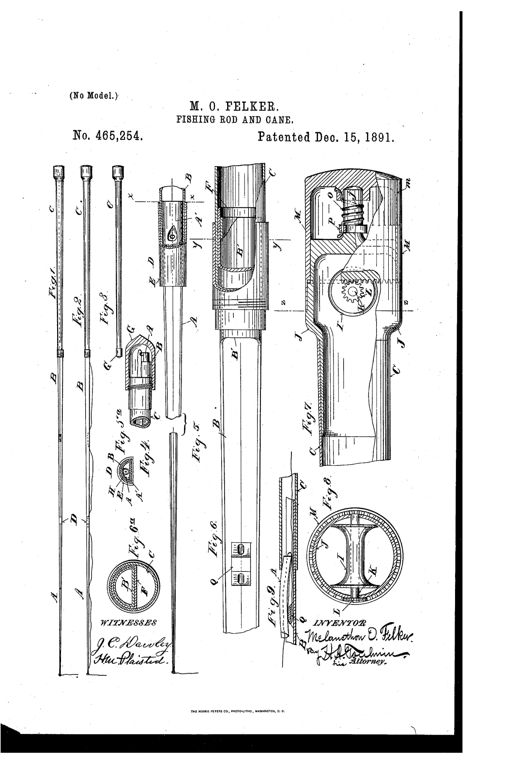
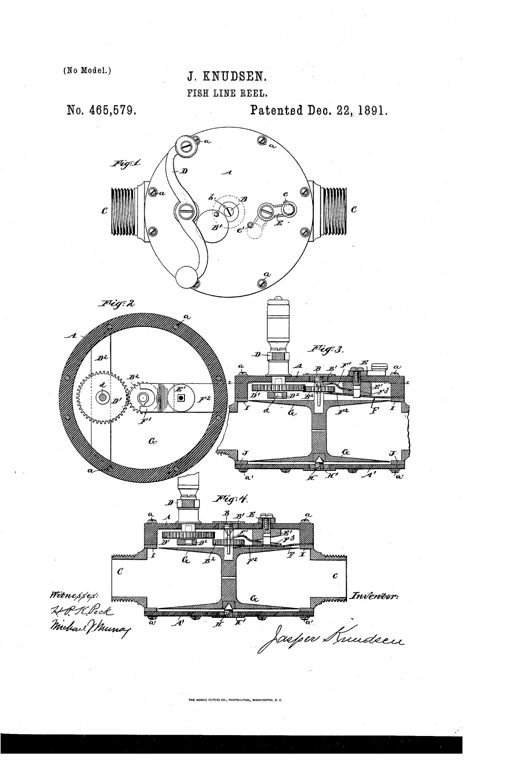
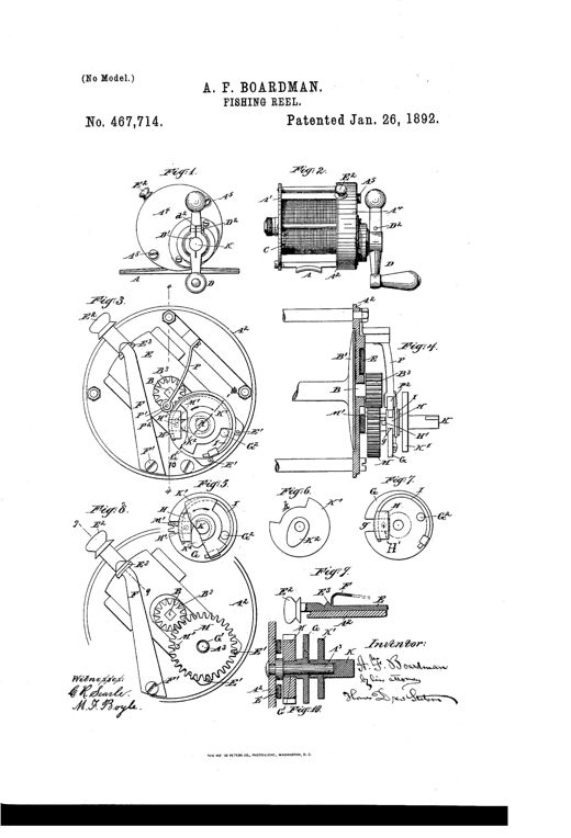
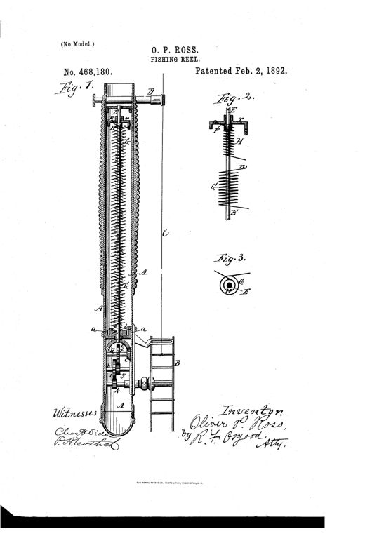
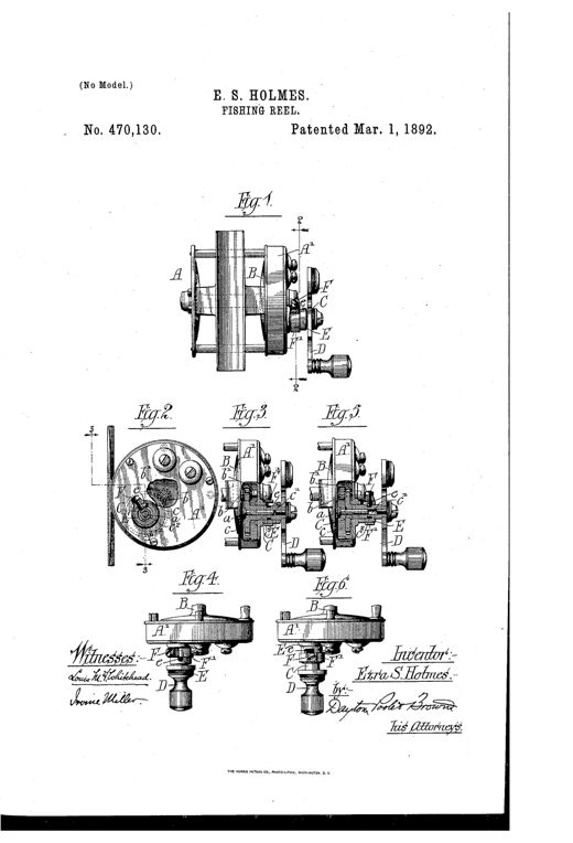
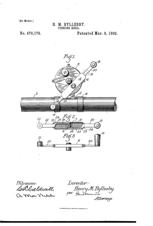
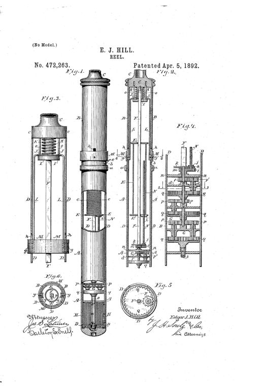
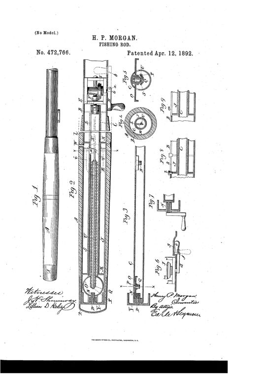
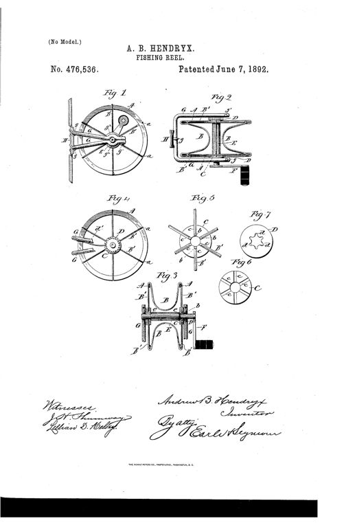
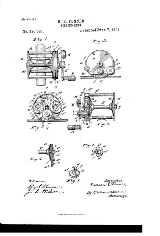
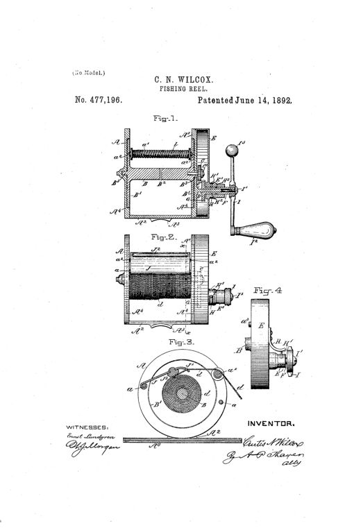
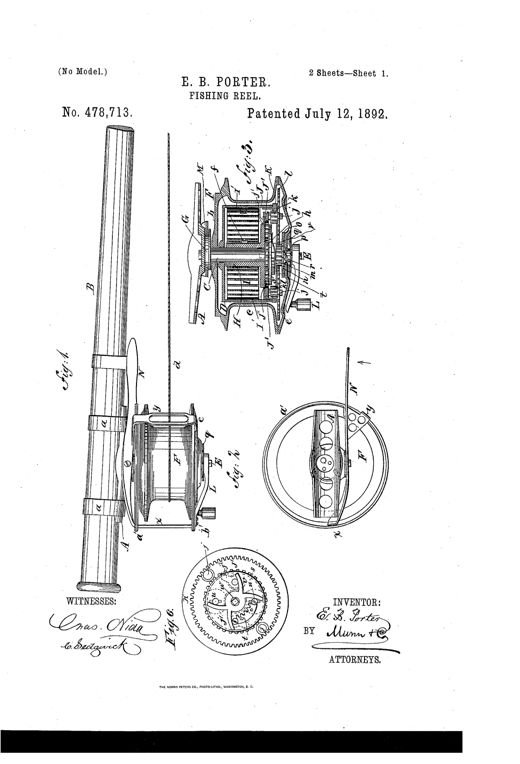
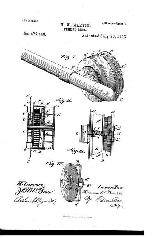
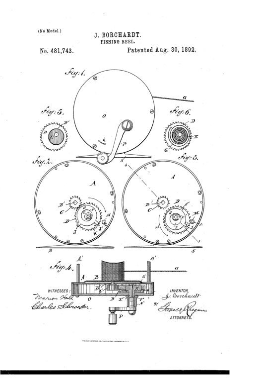
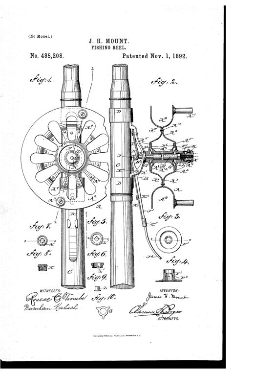
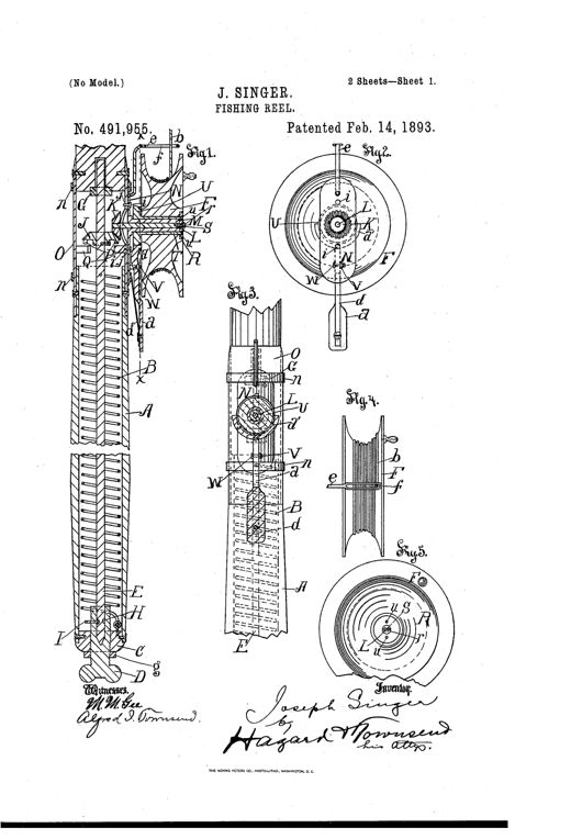
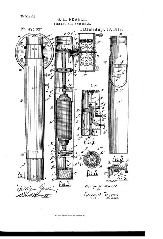
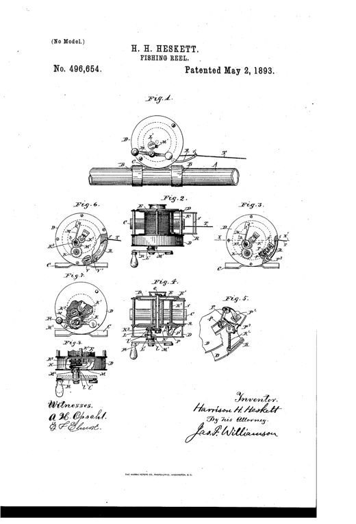
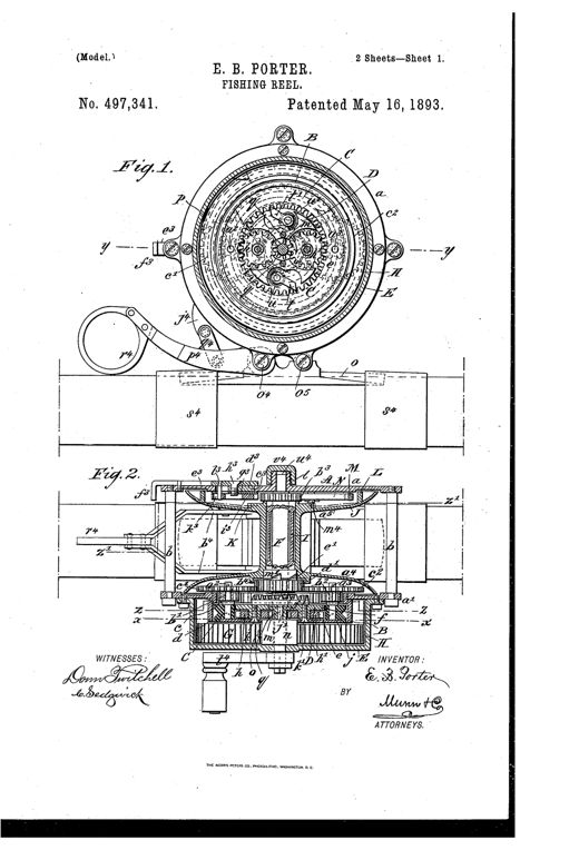
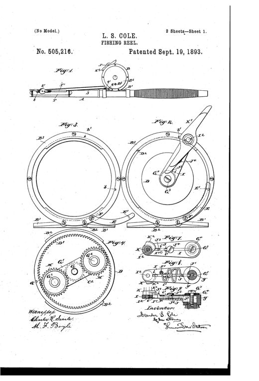
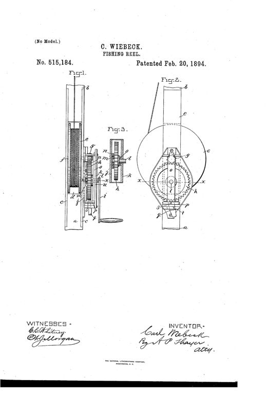
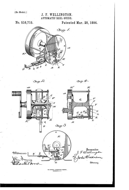
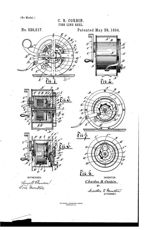
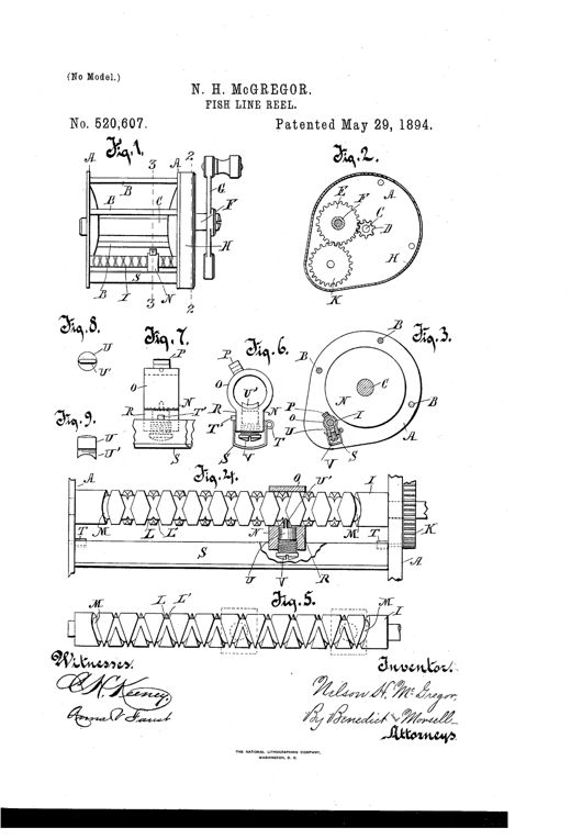
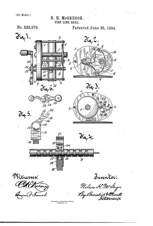
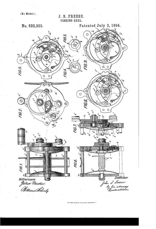
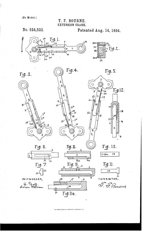
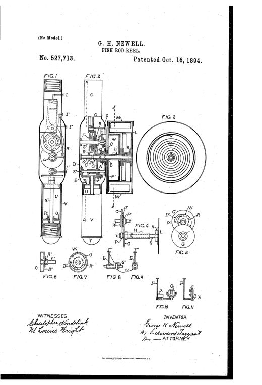
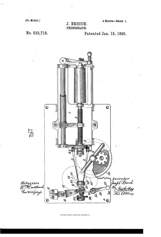
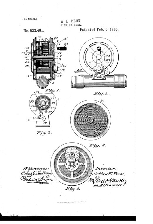
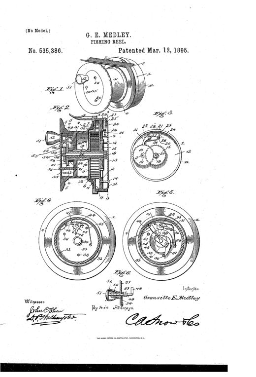
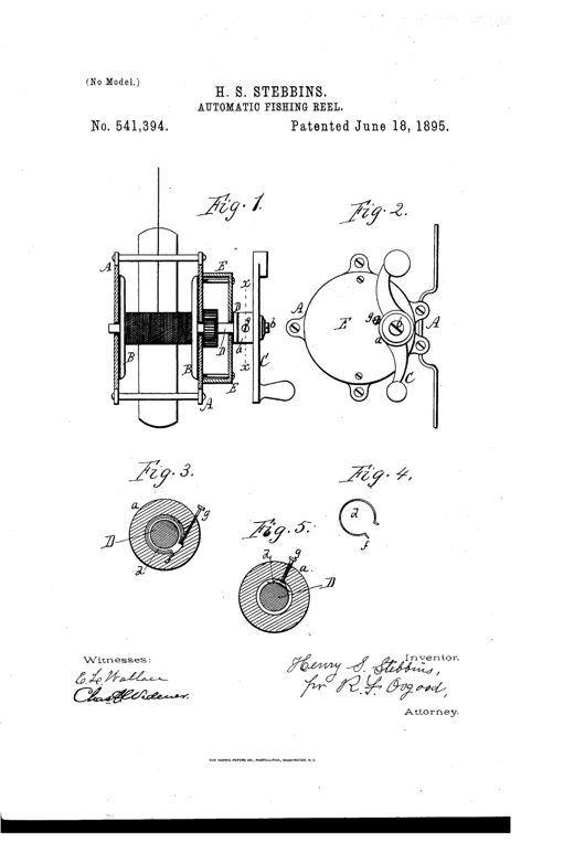
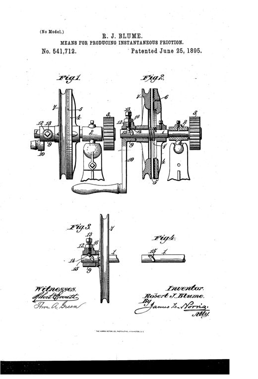
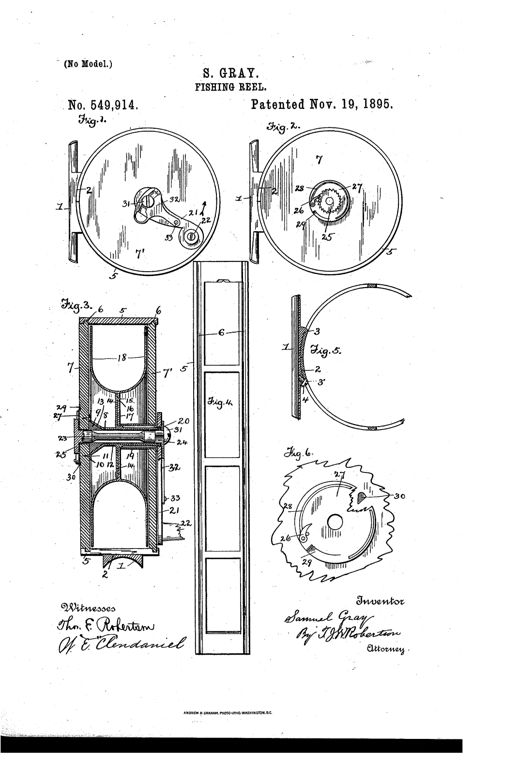
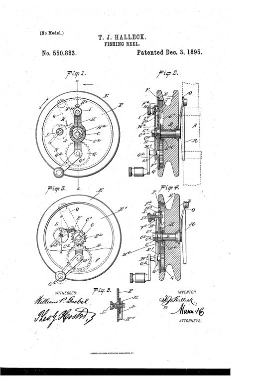
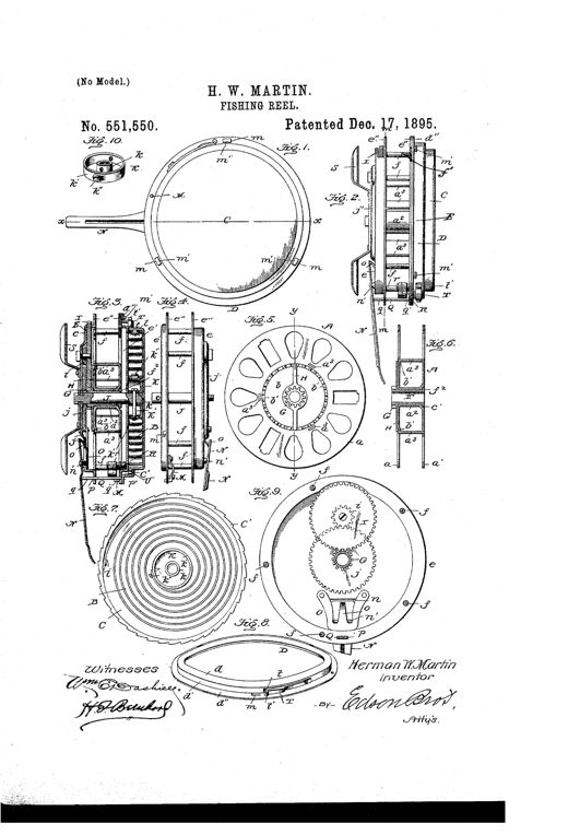
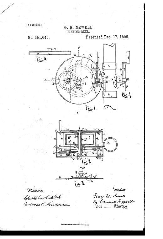
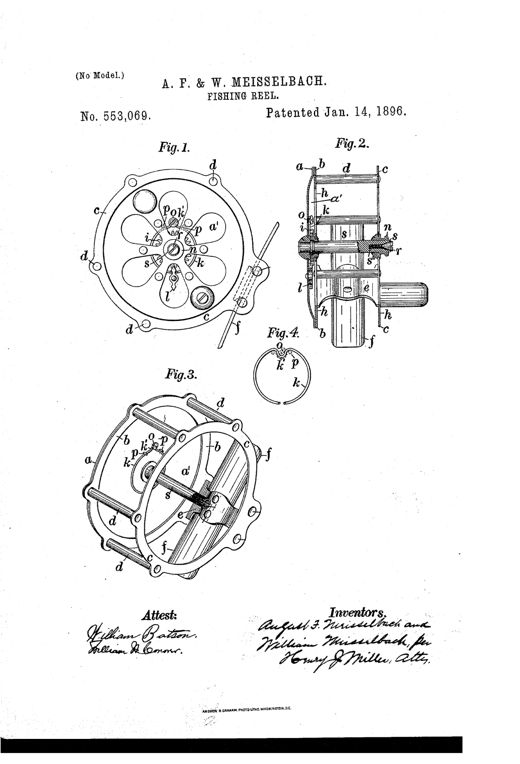
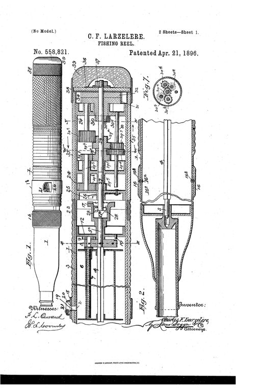
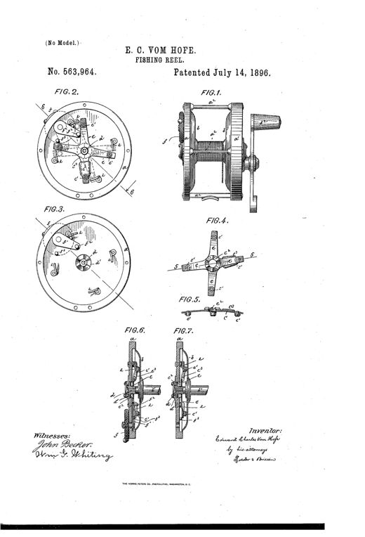
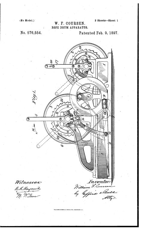
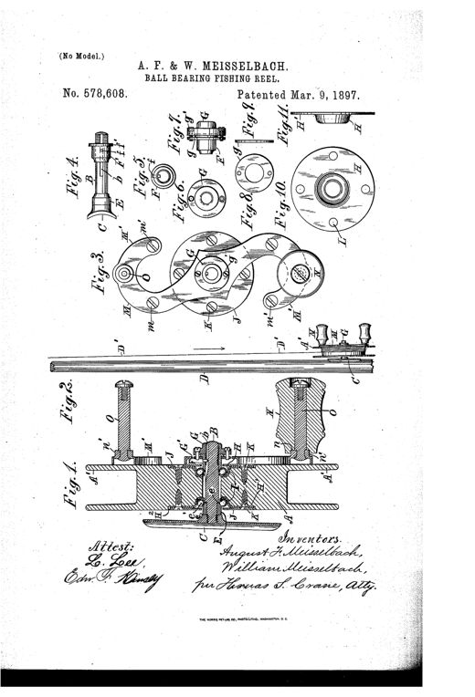
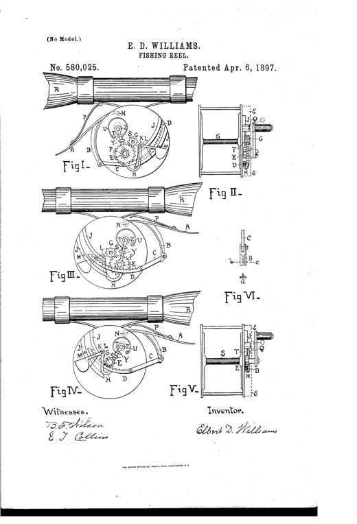
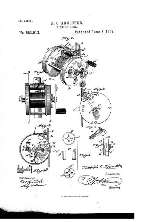
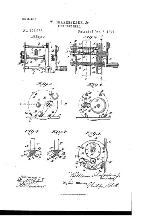
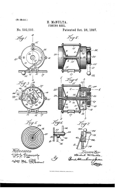
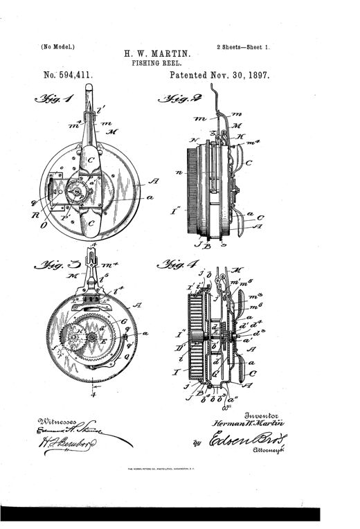
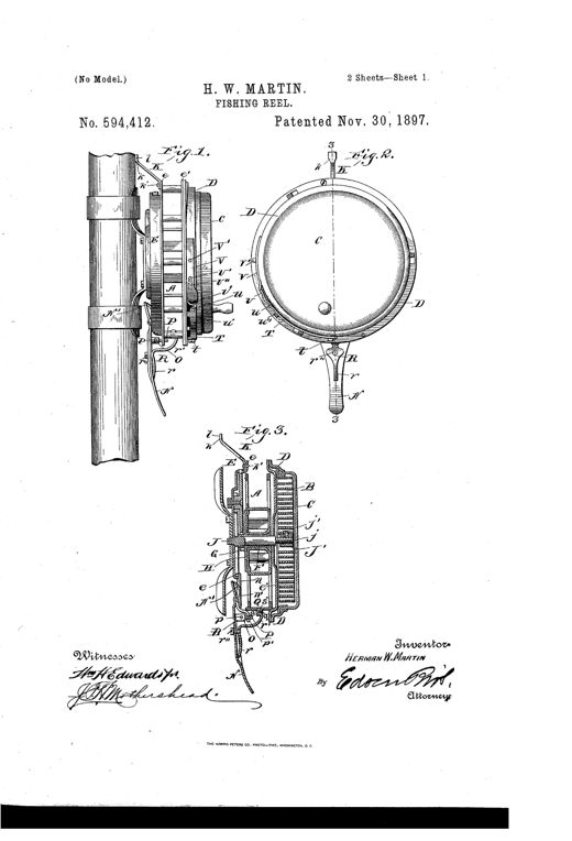
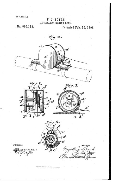
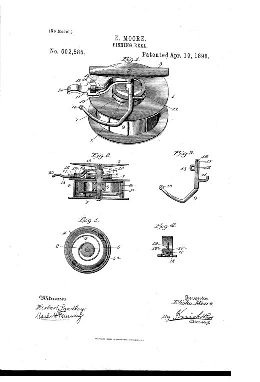
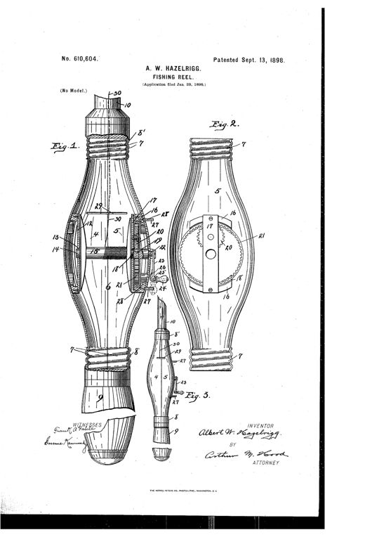
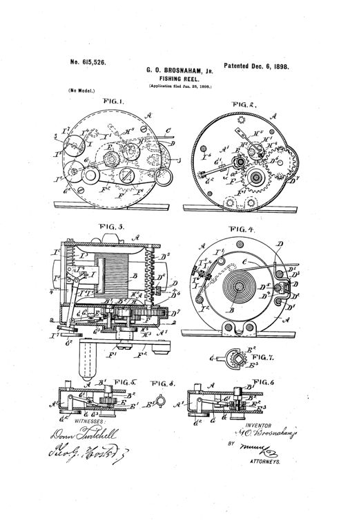
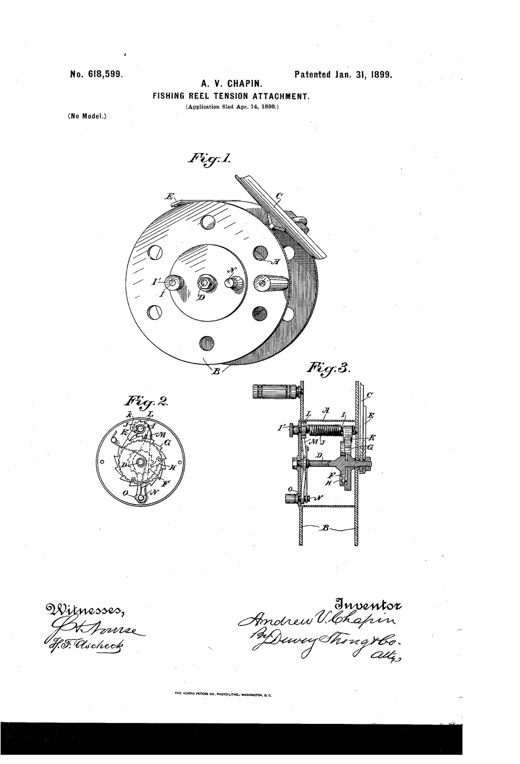
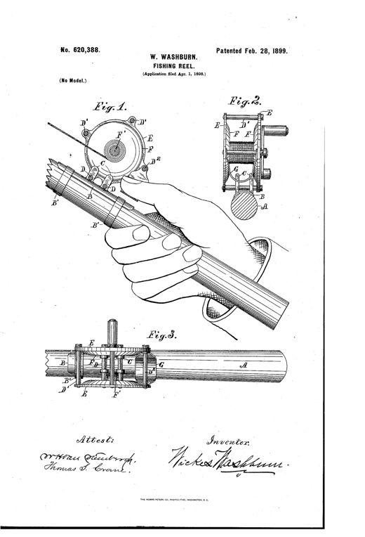
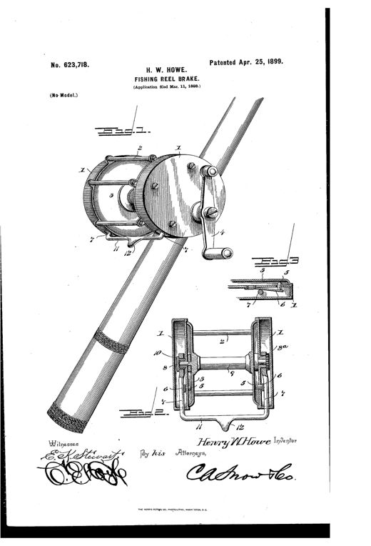
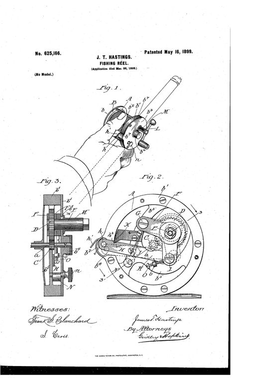
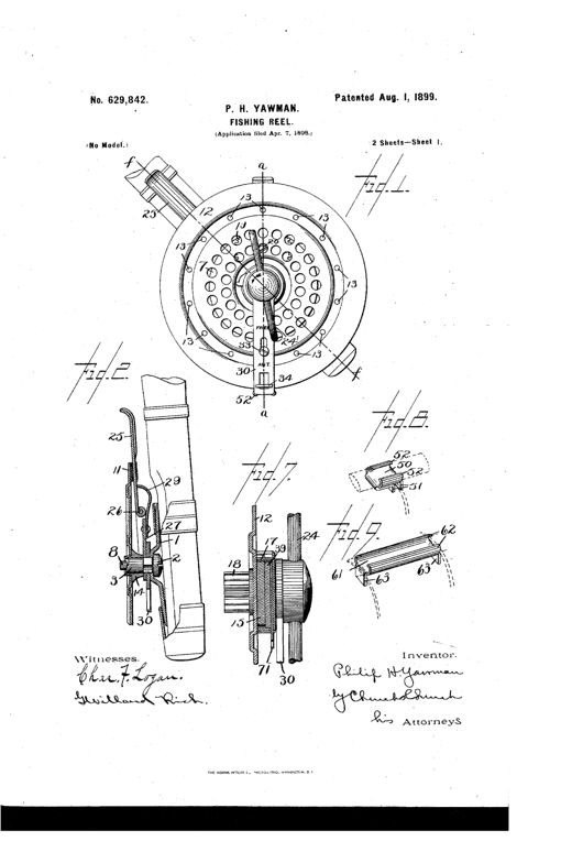
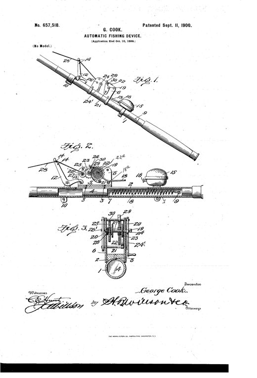
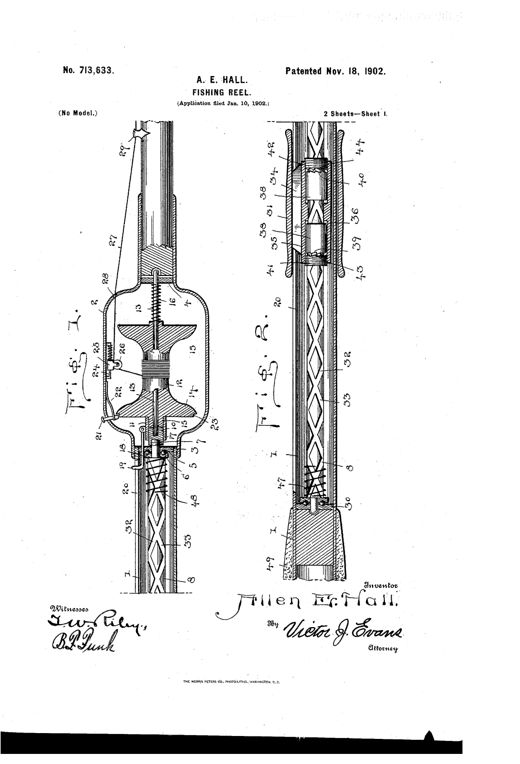
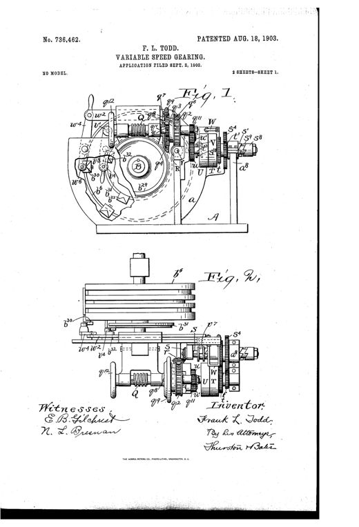
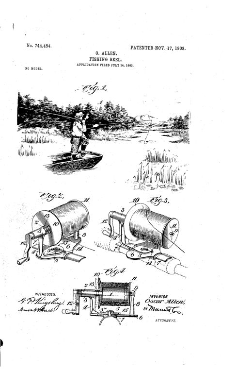
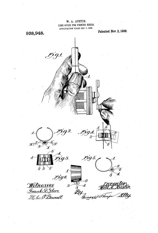
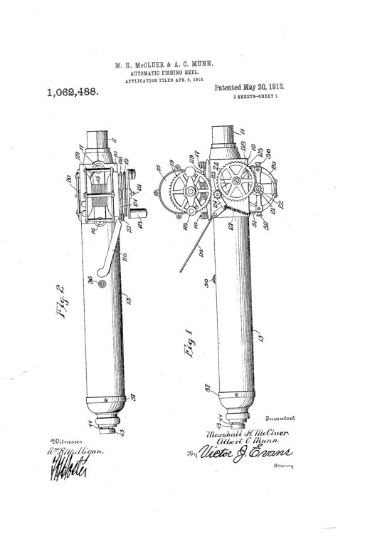
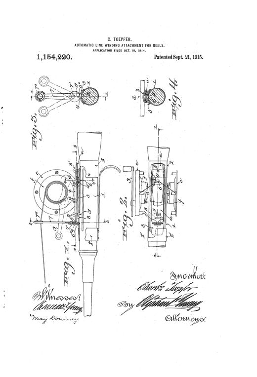
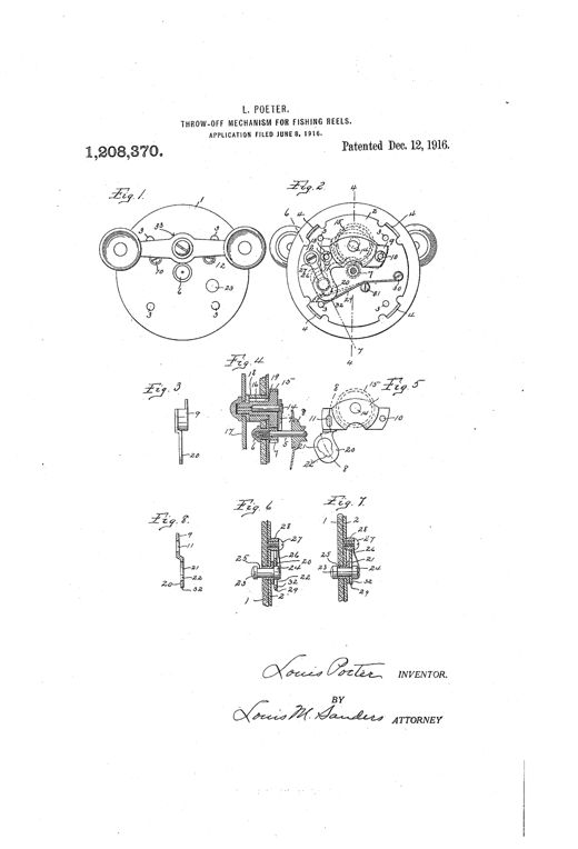
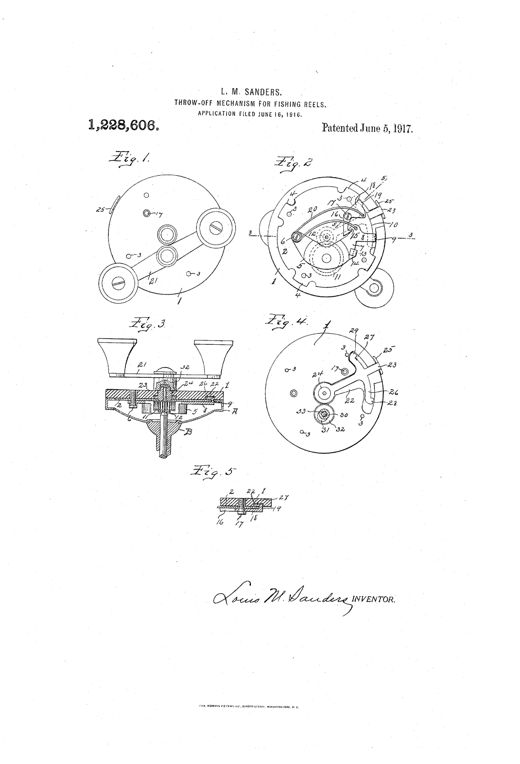
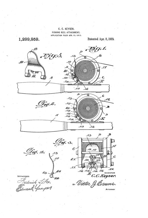
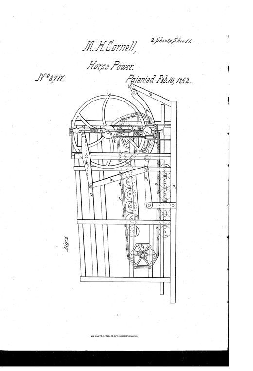
Two patent drawing sheets show a side and end elevation of a wooden-framed horse-power treadmill machine with an endless linked platform running over polygonal drums, fly wheels, a curved friction brake beam, and a ball-type centrifugal governor with connecting levers and rods.HORSE-POWERMartin Harris Cornell · February 10, 1852Patent drawing of a fishing reel in longitudinal section, showing the wound spool B inside frame A, with a bevel-pinion D, spring E, sliding hollow crank-shaft F, bevel-wheel G, and an offset crank handle H attached at the side.REEL FOR FISHING-RODS.John A. Bailey · August 5, 1856Patent drawing showing a circular skeleton fishing reel mounted on a rod section, with a central rotating disk, divided peripheral rings forming a tubular ring for line, and a side handle for winding, alongside detail views of the ring components and mounting plate.FISHING-REEL.William Billinghurst · August 9, 1859Patent drawing of a fishing reel mounted on a wooden post, showing a spool of line, a crank handle, and a sliding bar mechanism (Fig. 1), alongside a circular end view revealing the internal gear train (Fig. 2).IMPROVEMENT IN FISHING-REELS.Mark S. Palmer · February 28, 1860Patent drawing showing a hand gripping a fishing rod with a round reel attached (Fig. 1), a separate face view of the reel body (Fig. 2), and an end view of the reel with the cap removed exposing internal gearing and brake mechanism (Fig. 3).IMPROVEMENT IN FISHING-LINE REELSAndrew Dougherty · February 9, 1864Patent drawing showing a long cylindrical fishing pole casing containing an internal reel and gear mechanism, with a side crank handle and several cross-sectional views of the gear and clutch assembly labeled Fig. 1 through Fig. 5.IMPROVEMENT IN FISHING-LINE REELS.William M. Stuart · August 29, 1865Patent drawing of a windlass water elevator showing a well-curb frame with a shaft, rope drum, ratchet wheel, crank, and clamp mechanism, along with detailed close-up sections of the clamp and forked crank.IMPROVEMENT IN WATER-DRAWERSH. P. Castle · March 27, 1866Patent drawing of a fishing reel showing a circular skeleton spool with radiating ribs inside a banded frame, a crank handle, and a side view of the spool's stamped sheet-metal construction.IMPROVEMENT IN FISHING-REELS.Anson Hatch · June 19, 1866Cross-sectional line drawing of a fishing reel showing the spool D mounted between two head plates C and B, with gear teeth F, a crank handle G with wooden knob, and labeled parts including center pins E and E2, spindle H, and set-screw a, mounted on a vertical pillar frame A.IMPROVEMENT IN FISHING-LINE REELS.A. B. Hartill · August 7, 1866Two patent drawings of a 19th-century fishing reel: Fig. 1 shows a side sectional view of a round disk reel mounted on a foot-plate attached to a rod, with a small ball-tipped crank; Fig. 2 shows a top cross-section revealing two circular spool disks connected by a shaft, gears, and a crank handle above.Fishing-Line ReelWillard H. Bradley · September 22, 1868Patent drawing of a 19th-century multiplying fishing reel showing an assembled perspective view with crank handle, an internal gear view, a cross-section revealing the spool and pinion, and a detached bridge plate.IMPROVEMENT IN FISHING-REELS.Silas B. Terry · November 14, 1871Patent drawing of a 19th-century fishing reel showing a front elevation with hand crank and level-wind mechanism, plus two circular sectional views revealing internal gearing including a fan-shaped brake regulator, small pinions, and a spiral-grooved traversing screw for the line guide.IMPROVEMENT IN ANGLING-REELSCharles L. Noe · January 28, 1873Patent drawing showing a cutaway side view of a fishing reel with crank handle and internal gears (Fig. 1), and a front view of the reel's back plate exposing a set of interlocking gear wheels labeled H, I, J, K (Fig. 2).IMPROVEMENT IN FISHING-REELSCharles W. MacCord · February 10, 1874Patent drawing of a fishing reel mounted on a rod butt, showing a crank handle, two side disks, a hinged cover with sliding gate, and an axial line guide eye, plus a cross-sectional view of the internal shaft and disks.IMPROVEMENT IN FISHING-REELSThomas Winans and Thomas D. Whistler · March 23, 1875Two patent drawings of a fishing-rod handle with an internal reel: Figure 1 shows a front elevation with the rod tip, reel box, crank, and carved wooden handle, while Figure 2 shows a longitudinal cross-section revealing the circular reel with ratchet teeth and pawl inside the handle.IMPROVEMENT IN REELS FOR FISHING-RODSHezekiah Winslow · August 3, 1875Patent drawing of a circular fishing reel showing a perspective view with crank handle and cross-bar frame (Fig. 1), a cross-sectional side view (Fig. 2), and an internal view of the click mechanism with ratchet, dog, and spring (Fig. 3).IMPROVEMENT IN REELS FOR FISHING-LINESFrancis J. Philbrook · June 12, 1877Patent drawing of a fishing rod reel showing a metal reel-case with an internal geared spool, a folding crank handle that pivots into the rod, and a sliding line guide along a slotted case, with a separate close-up of the detachable crank and screw shaft.IMPROVEMENT IN FISHING-LINE REELS.George Trowbridge Copeland · September 25, 1877Patent drawing of a fishing rod segment showing an elongated winding-bar reel with crank set into a slotted section, alongside a sliding protective tube and end cap tackle compartment.IMPROVEMENT IN FISHING-RODSHenry Van Altena · October 1, 1878Patent drawing of a round fishing reel showing five figures: a side view with mounting foot, a front cross-section revealing the crank, spool-drum, and driving-shaft, two internal gear-train sections labeled with letters a through n, and a small circular detail of the click mechanism.IMPROVEMENT IN FISHING-REELSL. Taylor Dickson · April 22, 1879Patent drawing of a fishing reel mounted on a rod section, showing the spool, end plates, and a folding crank handle that locks against the frame to stop the line, with two smaller detail views of the crank mechanism below.Fishing-ReelGeorge Hancock · June 28, 1881Patent drawing sheet showing seven views of a circular fishing reel with an internal gear train, coil spring, spool, and side-mounted brake handle, labeled Figures 1 through 7.FISHERMAN'S REELFranklin R. Smith · July 26, 1881Patent drawing of a fisherman's reel showing an exploded mechanical view with a spooled reel attached to a wooden rod, gears, a coiled spring case, and detailed cross-sections labeled with reference letters like S, C, A, and G.FISHERMAN'S REEL.Franklin R. Smith · June 20, 1882Patent drawing showing a curved hand crank with a slotted or notched head (Figs. 1 and 2) that fits over a shaft pin, and a separate jam-nut with two long parallel ears (Fig. 3) used to lock the crank in place.CRANK AND CRANK FASTENING.Franklin F. Adams · September 19, 1882A sectional line drawing of a traction engine gearing assembly showing a main shaft A with fly-wheel D, pinion wheels B and C, spur-wheels K and K', a pillow-block F, and a connecting pin H fitted through aligned holes E, e, M, and m.TRACTION-ENGINEAbraham O. Frick · October 24, 1882Patent drawing of a circular centrifugal governor wheel with an internal spider arm, weighted pivoting levers, rock-arms, connecting rods, and friction bands wrapped around the wheel's rim, shown in perspective (Fig. 1) and rear plan view (Fig. 2).GOVERNOR FOR MECHANICAL POWERSJohn James Rufe · April 17, 1883Patent drawing of a cylindrical fishing reel showing its screw-threaded metal drum, cup-shaped end caps, internal spool and pinion gearing, and side crank handle.FISHING-REEL.George H. Palmer · July 24, 1883Patent drawing of a fishing reel showing a circular geared reel mounted in-line with a rod stock, with a side crank handle, gear wheel, pinion, and spring mechanism labeled with letters A through E.FISHING-REEL.John Dreiser · August 14, 1883Patent drawing showing a wood-handled fishing reel mounted between two rod sections, with side views revealing internal star-shaped and toothed gears, a crank handle, and a cross-sectional diagram labeling the spindle, gears, and slide mechanism.FISHING-REEL.Anton Lang · August 21, 1883Patent drawing showing a cylindrical casing with a hinged crank arm and pivoting handle that folds flat and stores inside the tube, with additional views showing the mechanism applied to a tape-line reel and a fishing-rod reel.CRANKJesse H. Burks · April 1, 1884Patent drawing sheets showing a circular flanged wheel with internal gripping levers and springs (Figs. 1 and 2), a cross-sectional side view (Fig. 3), a curved friction bow lever assembly (Fig. 4), and a sectional detail (Fig. 5), all part of an 1884 mechanical speed regulator.SPEED-REGULATOR.John H. Sharp · June 17, 1884Patent drawing showing a fishing reel with a coiled-wire spool mounted on a rod, an internal casing revealing a spring-driven gear and pinion mechanism, and detail views of the brake lever and pinion shaft.FISHING-REEL.Hiram Leroy Joslin · July 7, 1885Perspective patent drawing of a fishing reel mounted on a rod handle, showing the spooled reel, side frames labeled B, a crank with wooden handle, and a small line-guide pulley labeled G and E mounted on a cross-bar above the spool, with smaller detail figures below showing the pulley and bar mechanism.LINE-REEL FOR FISHING-TACKLE.Charles H. Briggs · September 8, 1885Technical patent drawing of a fishing-line reel showing a circular hinged frame mounted on a fishing rod, with a detachable spool, crank handle, and labeled parts a, b, c, d, e, k, n, q, r, s across six figures.FISHING-LINE REEL.Clarence V. Roberts · October 13, 1885Patent drawing of a fishing reel showing a spooled reel frame with a metal brake plate mounted above it, engaging beveled reel heads, alongside detail views of the brake mechanism and a spring-loaded pivoted variant.LINE-REEL BRAKECharles H. Briggs · November 3, 1885Patent drawing of a fishing rod whose hollow cigar-shaped butt conceals two chain-connected bobbins and multiplying gearing, operated by a finger ring protruding from the side of the butt, with a detailed cutaway showing gears, chain, crank, and a separate perspective view of the mechanism.FISHING ROD AND REEL.Abram H. Dailey · February 9, 1886Two long, tapering cutaway views of a fishing-pole butt containing internal reel bobbins, a toothed ratchet wheel, parallel rack bars on a sliding frame, guide rods, and a fingerhole lever at the base, alongside a small circular detail view of the bobbin hub.FISH-LINE REEL.Abram H. Dailey · February 9, 1886Patent drawing of a fishing-line transferring device showing two circular reel mechanisms mounted on a segmented wooden stick with labeled clamping rings, shafts, and a locking eccentric mechanism, alongside a top view of the same assembly with internal cross-rods and flanges visible.REEL FOR FISHING-RODS.Elisha J. Martin · February 9, 1886Patent drawing showing a round fishing reel with click and ratchet mechanism, a side view with foot, and an edge view of the reel mounted on a fishing pole held by a hand.FISHING-REEL.August F. Meisselbach · February 23, 1886Patent drawing of a wooden fishing reel with two crank handles, shown in cross-section to reveal an internal spindle riding on conical bearings and a threaded adjusting nut, alongside a separate ring-shaped clamp-sleeve for mounting the reel onto a fishing rod.FISHING-TACKLE.Gustav Ritter · June 1, 1886Patent drawing of a cylindrical fishing reel with a crank handle, showing internal spool, double-threaded transverse shaft, and a sliding line guide mechanism, along with several detailed cross-section figures of the gear and dog components.FISHING-REEL.Andrew B. Hendryx · October 26, 1886Patent drawing showing a hand gripping a fishing pole with a reel attached, alongside detailed mechanical views of the reel's spring-loaded drag mechanism with labeled parts including the foot, standard, spring, cross-bar, and thumb-piece.FISHING-REEL DRAG.August F. Meisselbach · November 23, 1886Patent drawing of a multiplying fishing reel showing an end view with crank handle, an exploded gear-train side view labeled with letters A through M, a perspective view of the frame without spool, and a separate figure-eight shaped retaining plate.FISHING-LINE REELWilliam B. Carpenter · August 16, 1887Patent drawing showing a fishing reel with a spool mounted in a ring frame, side bar with two sockets for attaching rod sections, and a spring drag mechanism with set-screw and thumb-piece.FISHING-LINE REEL.Erastus Titus, Jr. · September 6, 1887Patent drawing of a nineteenth-century multiplying fishing reel showing the side plates, hand crank, internal gear wheel and pinion, bow-spring drag lever with thumb piece, and click-spring mechanism labeled with reference letters across eight figures.FISHING-REEL.Thomas Henry Chubb · September 27, 1887Patent drawing of a Gibson fishing reel showing a round case with internal gear wheel, a swinging yoke holding the driving wheel, a brake lever, handle crank, and mounting foot, along with cross-section and end-plate views.FISHING-REELHenry B. Gibson · October 4, 1887Patent drawing sheets showing a fishing reel's internal spring barrel, planetary gear train, friction brake wheels, and toothed rings, with a side elevation of the assembled reel mounted on a rod handle and hand crank.FISHING-REEL.Elbert Ball Porter · December 6, 1887Patent drawing of an 1888 fishing reel showing a cutaway side section with internal spool, shaft, tension spring and friction ring, an end view of the assembled reel with handle and screws, and detail views of the friction ring and driving sleeve.FISHING-REEL.George S. Gates · January 31, 1888Patent drawing sheets showing a cylindrical fishing rod handle with a detachable multiplying reel, exploded and sectioned views revealing internal gearing, click wheel, spring drag, and threaded sockets connecting handle segments.COMBINED REEL-HANDLE AND FISHING-REEL.Abraham Coates · March 20, 1888Patent drawing sheet showing seven figures of a fishing reel: end and side views of the reel frame with barrel and spring, cross-sections revealing the internal spring and shaft, a detachable crank handle, and the journal shaft with pocket for the spring hook.FISHING-REEL.Charles K. Bradford · June 19, 1888Patent drawing of a cylindrical fishing reel showing a casing with spindle, spool with handle, retaining disks with click-pin, and a clamp for attaching to a fishing rod.FISHING-REEL.William A. Graham · July 24, 1888Patent drawing of an 1888 fish-line reel showing the reel mounted on a fishing rod, an exploded perspective of its spool, shaft, pulley and clutch sleeve, a cross-sectional view along the axis, and the bare frame with pillars and heads.FISH-LINE REELCharles F. Gillet · September 4, 1888Patent drawing of a fishing reel showing the winding drum with crank handle, an internal grooved cylinder mechanism for laying line evenly, and separate detail views of the tension yoke, guide bar, and pinion gearing.FISHING-REEL.Joseph Patrick Costigan · January 22, 1889Patent drawing of an 1889 fishing reel showing a circular side plate with internal gear and friction mechanism, a cross-sectional view revealing the spool, hub, and rod-mounting frame with concave arms, and a plan view of the handle assembly with locking bolt and thumb-operated disk.FISHING-REEL.George W. Prouty · January 29, 1889Patent drawing showing a hand gripping a fishing rod with an attached spool reel featuring a spoked flange and a thin metal drag band encircling its edge, alongside cross-sectional and detail views of the spool, post, and spring-loaded braking pin mechanism.FISHING-REELAugust F. Meisselbach and William Meisselbach · February 5, 1889Patent drawing of a fishing rod section showing a reel mounted on a reel-seat, with a curved wire lever and thumb-piece attached near the reel that guides the fishing line through an eye, alongside a separate detail view of the lever mechanism.LINE-GUIDE FOR FISHING-RODS.Charles H. Washburn · March 12, 1889Patent drawing sheet showing five figures of a fishing reel line-guide mechanism, including side and front elevations of small and large reels with a screw-cylinder, follower, guide tube, and crank, plus a detached perspective view of the guide tube with clamp pins.LINE-GUIDE FOR FISHING-REELS.Christian E. Moller and Charles Raettig · April 9, 1889Patent drawing sheet showing a fishing reel's internal gear train, spiral spring barrel, ratchet mechanism, brake levers, and the reel mounted on a fishing rod, with hand-labeled parts and inventor's signature.FISHING-REEL.Frank Carey · May 7, 1889Patent drawing sheet showing nine views of a multiplying fishing reel, including a perspective view with crank handle, side and end views revealing internal gears, and enlarged detail sections of the eccentric stud and tie-plate construction.FISHING-REEL.Charles K. Bradford · May 21, 1889Patent drawing showing an X-shaped folding wooden reel made of pivoted slats with pins at the ends, alongside a separate wire clamp with coiled springs and jaws for attaching the reel to a table edge, plus an enlarged cross-section of the central screw-pin assembly.REEL OR SWIFT.Herman Epple · September 3, 1889Patent drawing of a fishing reel showing the full assembled reel with spool and side plates (Fig. 1), an end-on view of the side plate with adjustment screw cap and pin (Fig. 2), and a cross-sectional view revealing the internal axle, pivot, sleeve-bearing, and screw-cap mechanism (Fig. 3).FISHING-REEL.Julius Vom Hofe · October 8, 1889Patent drawing of a Victorian fishing reel showing a front plan view with a spoked outer disk and central click mechanism, plus two side-section views revealing internal gears, screws, and a hollow oiling stud.FISHING-REEL.Charles M. Clinton · October 29, 1889Patent drawing of a fishing rod butt in longitudinal section showing an internal ferrule packed with stacked flanged rings and coiled springs connected by bevel gearing to an external cross-shaft spool, with a separate brake plunger mechanism and a cross-sectional view of the spring rings.FISHING-ROD AND REEL.Edward P. Follett · November 19, 1889Patent drawing of a fishing reel showing a circular end view with crank and gears, a longitudinal cross-section revealing the internal spool and brake mechanism, and an inner face view of the detachable end plate with ratchet and pawl.FISHING-REEL.Ernest Holzmann · March 4, 1890Patent drawing of a circular fishing reel mechanism showing internal gears, a pivoted bed-piece, and a spring-loaded clutch assembly labeled with letters A through K across six figures.FISHING-REEL.David Harris · July 1, 1890Patent drawing of a fishing rod showing a telescoping lower handle section, an internal rack-bar and gear mechanism, a reel mounted on the shaft, and cross-sectional details of the gears, pawls, and ratchets that convert sliding motion into reel rotation.COMBINED FISHING ROD AND REEL.Charles B. Corbin · September 9, 1890Patent drawing of a wooden-framed gear motor with a large cog-wheel and drum from which a weight hangs on a rope, alongside a smaller governor mechanism with a spring-loaded presser-foot pressing against a friction-wheel.MOTORHenry D. Deschler · November 25, 1890Patent drawing of a fishing rod segment with a reel mounted underneath, showing a mechanical brake attachment with curved arms and a lever positioned to press against the reel spool.FISHING-REEL ATTACHMENT.William H. Atkinson · December 9, 1890Patent drawing of a fishing reel showing seven diagrams: side and front elevations of the reel body, an internal view with the cap removed revealing the crescent-shaped spring brake-arm and gear, a detached view of the cap with its slotted operating-button, a cross-section through the cap and drum flange, and two additional views of an alternate brake-arm and button arrangement.FISHING-REEL.Andrew B. Hendryx · January 27, 1891Patent drawing of a circular fishing reel showing internal planetary gears, a brake ring, a click mechanism, and a crank handle mounted on a rod-plate with rings for attachment to a fishing rod.FISHING-REEL.Elbert B. Porter · February 17, 1891Patent drawing showing a jointed fishing rod with a hollow handle section containing an internal reel frame, gears, crank, alarm bell lever, and a friction brake knob, alongside exploded views of the gear and spool components.FISHING-RODLewis Wallace · September 29, 1891Patent drawing showing a side-mounted fishing reel with a spoked spool, a slotted cylindrical shell drag, a bent thumb-piece lever near the pole clamp, and detail views of the threaded stud and cone-piece assembly.FISHING-REEL.August F. Meisselbach and William Meisselbach · November 3, 1891Patent drawing sheets showing a fishing reel's internal gear mechanism including a circular gear-and-disk assembly, a longitudinal cross-section of the spool and crank-shaft, and a side elevation with visible cross-bars, click-wheel, and brake linkage.FISHING-REEL.William H. Atkinson · November 17, 1891Patent drawing showing a telescoping fishing rod and walking cane assembly, with labeled cross-sections of the semi-tubular rod joints, an internal reel mechanism inside the handle with a gear and pinion, and a signature block from the inventor Melancthon O. Felker.FISHING-ROD AND CANE.Melancthon O. Felker · December 15, 1891Patent drawing of a cylindrical fishing reel showing a top plan view with winding crank and rod couplings, plus two cutaway side sections revealing internal gear teeth, a shifting pinion, and a bifurcated spring mechanism used to engage or disengage the spool gearing.FISH-LINE REEL.Jasper Knudsen · December 22, 1891Patent drawing of a 19th-century fishing reel showing exterior views (Figs. 1-2) with crank and spool, and internal gear mechanism views (Figs. 3-10) illustrating the spur gears, cam-piece, locking pins, and sliding plate used to engage, disengage, and lock the spool.FISHING-REEL.Alphonso F. Boardman · January 26, 1892Patent drawing of a fishing rod butt in cross-section showing nested spiral springs, a central spindle, bevel and spur gears, and an external winding spool with handle.FISHING-REELOliver P. Ross · February 2, 1892Patent drawing of a fishing reel showing the frame, spool, crank handle, and internal gear mechanism in six labeled figures illustrating engaged and disengaged positions.FISHING-REEL.Ezra S. Holmes · March 1, 1892Patent drawing showing a cylindrical fishing reel mounted on a segmented fish-pole via sliding collars, with an angled crank handle extending from the reel body, plus two additional sectional views below showing the telescoping crank arm with internal rack-and-pinion gearing and a counterbalancing weight knob.FISHING-REEL.Henry M. Byllesby · March 8, 1892Patent drawing of a fishing rod handle in cross-section showing an internal spring-driven winding spool, gear train, threaded shaft, and sliding control band, with six labeled figures illustrating the mechanism.REEL.Edgar J. Hill · April 5, 1892Patent drawing of a fishing rod butt section shown in full side view and in longitudinal cross-section, revealing an internal tubular shaft, spool, gears, sprocket wheels, endless chain, and a side-mounted crank handle, with several smaller detail views of alternate mechanisms.FISHING-ROD.Henry P. Morgan · April 12, 1892Patent drawing of a wire-frame fishing reel showing the spoked spool with wire loops, the stirrup-shaped side frames, crank handle, and detailed hub and ratchet mechanisms in separate small figures.FISHING-REELAndrew B. Hendryx · June 7, 1892Patent drawing sheet showing seven mechanical views of a fishing reel, including plan and end views, internal gear and cam sections, and isolated parts like the click disk, drag cam, and handle cog-wheel, all labeled with reference letters.FISHING-REEL.Richard E. Fenner · June 7, 1892Patent drawing of a fishing reel showing a cutaway frame with spool, sliding pinion sleeve, crank handle assembly, and a separate detail view of an assembled cylindrical reel with a hinged brake arm crossing the wound line.FISHING-REEL.Curtis N. Wilcox · June 14, 1892Patent drawing sheets showing a spring-powered fishing reel with internal planetary gear train, cam-actuated clutch disk, hand crank, brake lever with wire line guard, and exploded views of individual gears and pinions.FISHING-REEL.Elbert Ball Porter · July 12, 1892Patent drawing of a cylindrical fishing reel mounted on a rod, showing an external winding wheel with radiating spokes and teeth on one end, internal gear train and coiled spring barrel visible in cutaway views, and a separate brake pin mechanism, with a modified deep-water version featuring a line guide and cam assembly.FISHING-REEL.Herman W. Martin · July 26, 1892Patent drawing sheet showing six views of a fishing reel: a full side view with crank handle labeled Fig.1, two side views of internal gearing with cog-wheels and pinions engaged and disengaged labeled Fig.2 and Fig.3, a cross-sectional end view labeled Fig.4, and two small detail views of the eccentric disk and cog-wheel labeled Fig.5 and Fig.6.FISHING-REEL.John Borchardt · August 30, 1892Patent drawing showing a fishing reel mounted on a rod, with a spoked bobbin wheel, a lever-and-spindle brake mechanism, and several small detail views of the friction plates, collar, nut, and spring components.FISHING-REEL.James H. Mount · November 1, 1892Patent drawing sheets showing cross-sections and elevations of a spring-actuated fishing reel with a hollow rod handle housing a coiled spring, gear train, friction brake wheel, and a detachable reel plate with labeled parts A through W and section views Fig.1 through Fig.6.FISHING-REELJoseph Singer · February 14, 1893Patent drawing of a fishing rod butt with an internal reel mechanism, showing cross-sections of the cylindrical shell with a coiled spring, shafts, bevel gears, a ratchet wheel with pawl, and lever and button controls for engaging or disengaging the spring-driven reel, with a signed inventor's name and witness signatures at bottom.FISHING ROD AND REEL.George H. Newell · April 18, 1893Patent drawing of a fishing reel mounted on a pole, showing the circular reel case with internal gears, a pivoted brake shoe and trip lever, plus several detail views of the brake and gear-shifting mechanism.FISHING-REEL.Harrison H. Heskett · May 2, 1893Patent drawing of a spring-powered fishing reel showing a circular gear train inside a housing with pillars, a folding crank handle, and cross-sectional views revealing internal spur wheels, pinions, and a volute spring mechanism.FISHING-REELElbert B. Porter · May 16, 1893Patent drawing of an 1893 tarpon fishing reel mounted on a pole, showing the crank handle, side plates with screws, internal gearing, brake band mechanism, and a separate thumb-piece connected by a cord running along the rod handle.FISHING-REEL.Leander S. Cole · September 19, 1893Patent drawing of a fishing rod reel showing the internal gear mechanism, including a pinion and master wheel with crank, mounted between metal side plates, with three figures illustrating the plan view, side elevation, and cross-section of the driving gear case.FISHING-REELCarl Wiebeck · February 20, 1894Patent drawing of a fishing reel with an automatic line guide, showing internal cog wheels, a pivoting arm, and an adjustable slotted arm mounted on the reel's side plate, alongside plan and sectional views of the gear mechanism.AUTOMATIC REEL-GUIDE.J. Farnum Wellington · March 20, 1894Patent drawing sheet showing six technical figures of a spring-driven fishing reel with internal gear train, ratchet drum, brake lever, and folding hand crank, labeled with reference letters A through P.FISH-LINE REEL.Charles B. Corbin · May 29, 1894Patent drawing sheet showing a classic bait-casting style fish-line reel in side elevation (Fig. 1) with end plate, crank handle, and internal spool, plus a gear-train cutaway (Fig. 2), a reversely-grooved worm shaft with a traveling guide ring and hinged cap (Figs. 3-9), all labeled with reference letters A through V.FISH-LINE REELNelson H. McGregor · May 29, 1894Patent drawing sheet showing six figures of a fishing reel: a front elevation with crank handle and end plates, an end view revealing internal gears and pinion, a cross-section through the spool and grooved shaft, a detail of the reversely grooved shaft with a sliding guide, a small forked guide ring, and a simple crank handle.FISH-LINE REEL.Nelson H. McGregor · June 26, 1894Patent drawing sheet showing nine mechanical diagrams of a fishing reel's internal gear, cam, click, and drag mechanism, plus two side-view assemblies of the full reel with spool and crank handle.FISHING-REEL.John S. Freese · July 3, 1894Patent drawing sheet showing multiple side views and cross-sections of a two-part telescoping bicycle crank with pedal, pin, spring, and locking recess details labeled with numbered reference lines.EXTENSION-CRANK.Theodore F. Bourne · August 14, 1894Patent drawing of a fishing rod handle in longitudinal section showing an internal clock-spring reel mechanism with gears, ratchets, a friction brake, and a separate circular reel view, alongside several small detail figures of coupling and clutch parts.FISH-ROD REEL.George H. Newell · October 16, 1894Patent drawing of a phonograph mechanism showing a vertical governor shaft with weighted bell-crank arms, an adjustable cone brake, belt-and-pulley speed transmission, and a spring-driven going-barrel with gear train, mounted on a rectangular base plate.PHONOGRAPH.Joseph Broich · January 15, 1895Patent drawing of a spring-powered fishing reel showing an exploded end view with internal gears, a spring barrel, a centrifugal pawl-and-ratchet clutch disk, a brake lever, and a side elevation of the assembled reel attached to a rod section.FISHING-REEL.Arthur E. Peck · February 5, 1895Patent drawing of a cylindrical fishing reel shown in perspective and in several cutaway cross-sections revealing an internal spiral spring, gear train, clutch plate, click wheel, and crank handle mechanism.FISHING-REEL.Granville E. Medley · March 12, 1895Patent drawing showing a fishing reel in longitudinal section with labeled frame, spool, gearing, crank, and a friction spring inside the crank hub, plus enlarged cross-section views of the spring mechanism.AUTOMATIC FISHING-REEL.Henry S. Stebbins · June 18, 1895Patent drawing showing a shaft-mounted friction clutch mechanism with two pulleys, a spiral-grooved shaft, spring, crank handle, and detail views of the sleeve and channel components.MEANS FOR PRODUCING INSTANTANEOUS FRICTION.Robert J. Blume · June 25, 1895Patent drawing sheet showing six figures of a late 19th-century fishing reel: front and rear elevations with numbered parts like ratchet wheel, pawl, and crank-arm, a sectional view of the drum interior, a flat blank pattern for the drum strip, a side clamp section, and a detailed close-up of the washer and notch mechanism.FISHING-REEL.Samuel Gray · November 19, 1895Patent drawing sheet showing a round fishing reel viewed face-on (Figs. 1 and 3) with internal gears, a pinion, sliding arm, click pawl and crank handle, plus corresponding cross-section views (Figs. 2 and 4) revealing the pivot, pulley hub, gear-wheel and mounting plate attached to a fishing rod, and a small detail view (Fig. 5) of the retarding pawl mechanism.FISHING-REEL.Thomas J. Halleck · December 3, 1895Patent drawing sheet showing ten labeled figures of a circular fishing reel with an exposed spring drum, gear train, line spool with tongues and notches, brake lever mechanism, and detachable clamping ring, alongside a signed inventor's certification block.FISHING-REEL.Herman W. Martin · December 17, 1895Patent drawing showing a cylindrical fishing reel with internal gears, a hollow shaft, spring casing, clutch mechanism, and brake assembly, along with cross-sectional views labeled Fig. 1 through Fig. 5.FISHING-REEL.George H. Newell · December 17, 1895Patent drawing of a Meisselbach fishing reel showing the cheek plate with internal click mechanism, an edge cross-section revealing the spool and spindle, a perspective view of the frame with spool removed, and a detail of a modified click-spring.FISHING-REEL.August F. Meisselbach and William Meisselbach · January 14, 1896Patent drawing of a fishing rod butt shown in cross-section, revealing an internal spindle, sliding reel, ratchet wheels, and a multiplying gear train housed within the hollow cylindrical butt, with an oscillating sleeve and screw cap at the rear end.FISHING-REEL.Charles F. Larzelere · April 21, 1896Patent drawing showing a cylindrical fishing reel with two side plates connected by pillars, a crank handle, and an internal spider-shaped brake mechanism with toothed jaws visible in cutaway face views.FISHING-REELEdward Charles Vom Hofe · July 14, 1896Patent line drawings of a derrick rope-drum apparatus showing two large friction drums mounted on a vertical frame, with hand levers, a band brake, ratchet wheels, and a foot-lever and counterweight mechanism for controlling drum rotation.ROPE-DRUM APPARATUS.William F. Coursen · February 9, 1897Patent drawing sheet showing a wooden fishing reel assembly in cross-section (Fig. 1-2) mounted on a fishing pole with a stud, cones, and ball-bearing races, plus detail views (Fig. 3-11) of the crank-plate, adjusting cones, nuts, collars, and stamped sheet-metal ball-race components.BALL-BEARING FISHING-REEL.August F. Meisselbach, William Meisselbach · March 9, 1897Patent drawing showing a fishing rod section with an attached reel mechanism, illustrating internal gears, a ratchet wheel, a reciprocating rack-bar, and a lever labeled with letters A through Z across six numbered figures.FISHING-REEL.Elbert D. Williams · April 6, 1897Patent drawing of a Kruschke fishing reel showing an exploded perspective view with crank handle, internal gears, spool shaft, cam cylinder, and level-wind guide arm, alongside cross-sectional and detail views of the brake and gear mechanisms.FISHING-REEL.Rudolph C. Kruschke · June 8, 1897Patent drawing sheet showing seven figures of a fishing reel with side plates, cross-bars, grooved spindles, a crank handle, gear casing, and a click mechanism, labeled with letters A through Z identifying each part.FISH-LINE REEL.William Shakespeare, Jr. · October 5, 1897Patent drawing sheet showing seven figures of a mechanical fishing reel with a crank handle, spool, drum, ratchet wheel, pawls, and internal spring mechanisms, labeled with numbered reference parts.FISHING-REEL.Herbert McNulta · October 26, 1897Patent drawing sheets showing a circular fishing reel housing with internal gear train, crank-arm, dual brake jaws, a spring-loaded indicator dial, and a curved segmental line guide, accompanied by detail views of gears, jaws, and spool disks.FISHING-REELHerman W. Martin · November 30, 1897Patent drawing showing a fishing reel mounted on a pole with exploded and sectional views revealing the internal spring-loaded brake lever, ratcheted mainspring drum, and line-spool components labeled with reference letters.FISHING-REEL.Herman W. Martin · November 30, 1897Patent drawing showing a cylindrical fishing reel with a winding spool mounted on a fishing rod, plus internal gear and brake mechanism views labeled with reference letters.AUTOMATIC FISHING-REEL.Fayette J. Boyle · February 15, 1898Patent drawing of a fishing reel mounted on a rod plate, showing an internal coiled spring, a cam-grooved drum, a swinging line guide arm with an eye, and a separate brake mechanism with a friction roller and ratchet teeth.FISHING-REELElisha Moore · April 19, 1898Patent drawing showing a bulb-shaped fishing reel split into two hollow sections with an internal bobbin, gears, and a pivoting crank handle, alongside a smaller side view of the assembled reel attached to a rod.FISHING-REELAlbert W. Hazelrigg · September 13, 1898Patent drawing sheet showing eight numbered figures of a geared fishing reel, including side and sectional views revealing internal gear wheels, a clutch pinion, a brake lever with shoe, a screw-spindle level-wind guide, and a small pinion detail, with inventor's signature and witness signatures at bottom.FISHING-REEL.George O. Brosnaham, Jr. · December 6, 1898Patent drawing of a fishing reel showing a circular barrel with internal ratchet wheels and pawls (Figs. 1 and 2), and a cross-sectional side view (Fig. 3) revealing the shaft, spring, and thumb-adjustment knob for tension control.FISHING-REEL TENSION ATTACHMENT.Andrew Verd Chapin · January 31, 1899Patent drawing showing a fishing reel mounted on a rod butt held in a hand, with an exploded edge view and a plan view revealing internal tie-rods, lugs, and spool flanges labeled with letters A through G.FISHING-REELWickes Washburn · February 28, 1899Patent drawing of a fishing reel mounted on a rod, showing the crank, spool, and two spring-loaded brake arms with a thumb button on a cross-bar, plus enlarged cutaway views of the brake-shoe mechanism.FISHING-REEL BRAKE.Henry W. Howe · April 25, 1899Patent drawing showing a fishing reel mounted on a rod held by a hand, with Fig. 1 illustrating the exterior view including thumb-piece and crank, Fig. 2 showing the internal gear mechanism with pinions, yoke, and thrust-rod exposed, and Fig. 3 depicting a cross-sectional view of the reel's internal shaft and locking components.FISHING-REEL.James T. Hastings · May 16, 1899Patent drawing of an automatic spring-wound fishing reel showing a side elevation mounted on a rod section with numbered pillars, screws, and a brake lever, plus cross-sectional views revealing internal gearing, ratchet wheels, and a coiled mainspring.FISHING-REEL.Philip H. Yawman · August 1, 1899Patent drawing of a fishing rod fitted with a casing containing a spring, gear train, alarm bell, and crank-operated reel, shown in perspective and in longitudinal and cross-sectional views.AUTOMATIC FISHING DEVICE.George Cook · September 11, 1900Patent drawing of a fishing rod with an internal reel mechanism, showing the spool, ratcheted collars, coil springs, sliding operating sleeve, and a full rod assembly with line looped through guides to a hand grip at the butt.FISHING-REELAllen E. Hall · November 18, 1902Mechanical drawing of a variable-speed gearing apparatus showing a main shaft with worm-wheel, cam-wheels, hand-wheels, belt-pulleys, and a spindle with sliding gear sleeves and clutch collars, labeled with numerous reference letters and numbers.VARIABLE-SPEED GEARINGFrank L. Todd · August 18, 1903Patent drawing showing a man fly-fishing from a small boat with a pivoting reel labeled Fig. 1, plus three detailed mechanical views (Figs. 2-4) of the reel's spool, crank, pivot post, and coil spring assembly.FISHING-REEL.Oscar Allen · November 17, 1903Patent drawing showing a hand gripping a fishing rod with a small split-thimble line guide clipped over the thumb, alongside detail views of the guide's flaring passage and lug from several angles.LINE-GUIDE FOR FISHING-REELS.Will A. Austin · November 2, 1909Patent drawing of a fishing rod handle and head showing an electric motor, gear train, toothed wheels, and a swinging operating lever connected to a reel, with a cross-section revealing an internal battery in the tubular handle.AUTOMATIC FISHING-REELMarshall H. McCluer and Albert C. Munn · May 20, 1913Patent drawing showing a fishing rod section with an oscillating reel frame, pivoting saddle foot, crank handle, and a line-guiding lever with an eye at its tip, illustrated in side, plan, and cross-sectional views.AUTOMATIC LINE WINDING ATTACHMENT FOR REELS.Charles Toepfer · September 21, 1915Patent drawing of a fishing reel head plate assembly showing a front view with two spool ends and crank, a detailed rear view of the gear train and pivoted bridge with numbered parts, and several cross-section diagrams illustrating the push-pin locking mechanism in engaged and disengaged positions.THROW-OFF MECHANISM FOR FISHING-REELSLouis Poeter · December 12, 1916Patent drawing sheet showing five figures of a fishing reel head-plate mechanism: a front face view with spool and handle, a rear view revealing a pivoted bridge, gears, hooks and a coil spring, a cross-sectional side view, another rear view with the gears removed showing the manually operated lever and arc-shaped arms, and a small cross-section detail.THROW-OFF MECHANISM FOR FISHING-REELS.Louis M. Sanders · June 5, 1917Patent drawing showing a fishing reel mounted on a rod handle, with a curved metal plate and coil spring attachment pressing against the spool, plus close-up detail views of the plate, latch, and spring mechanism.FISHING-REEL ATTACHMENT.Charles C. Keyser · April 8, 1919