FISHING-REEL.
A planetary gear train hides inside the crank cap, switchable to single-action

Multiplying fishing reel with planetary gear train
↻ How it works
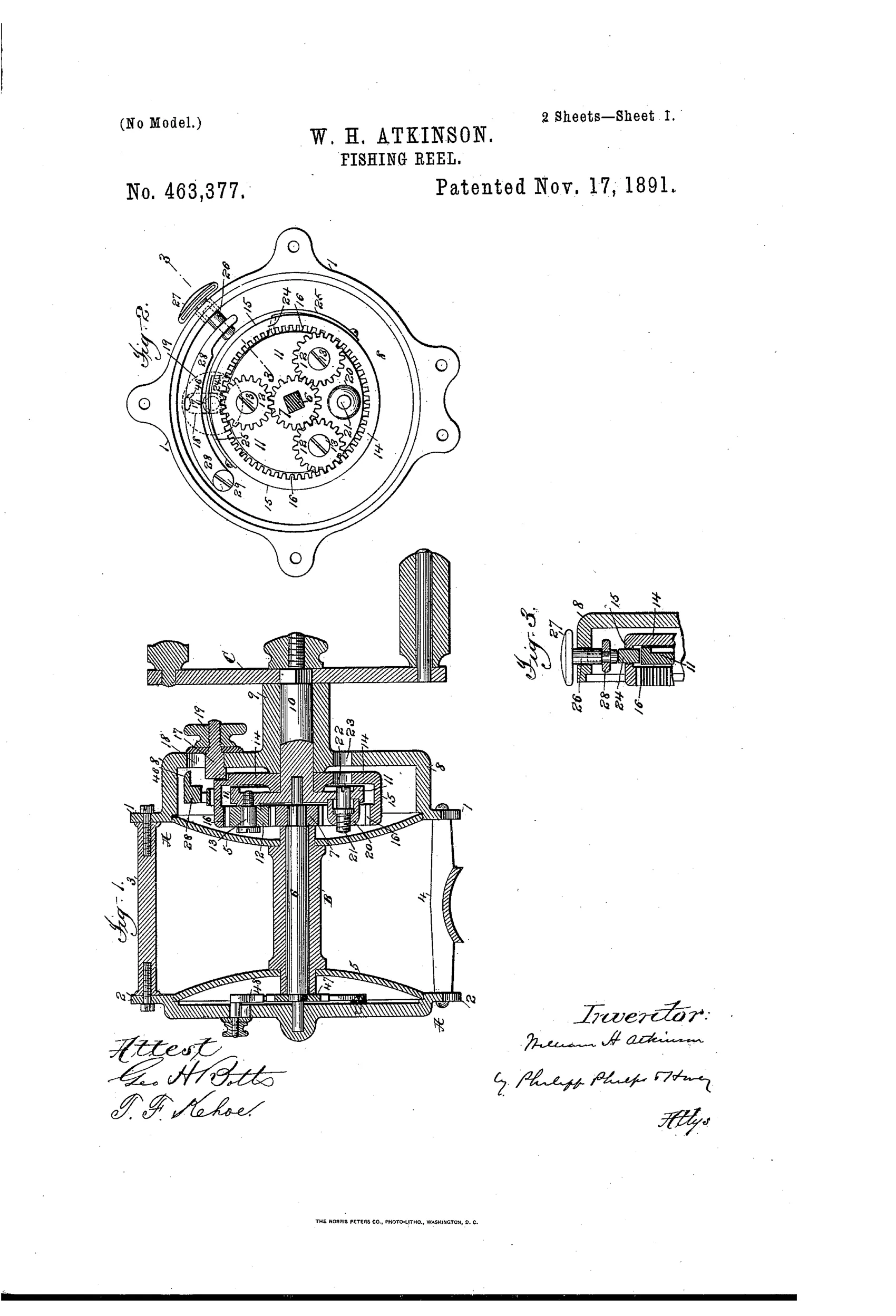
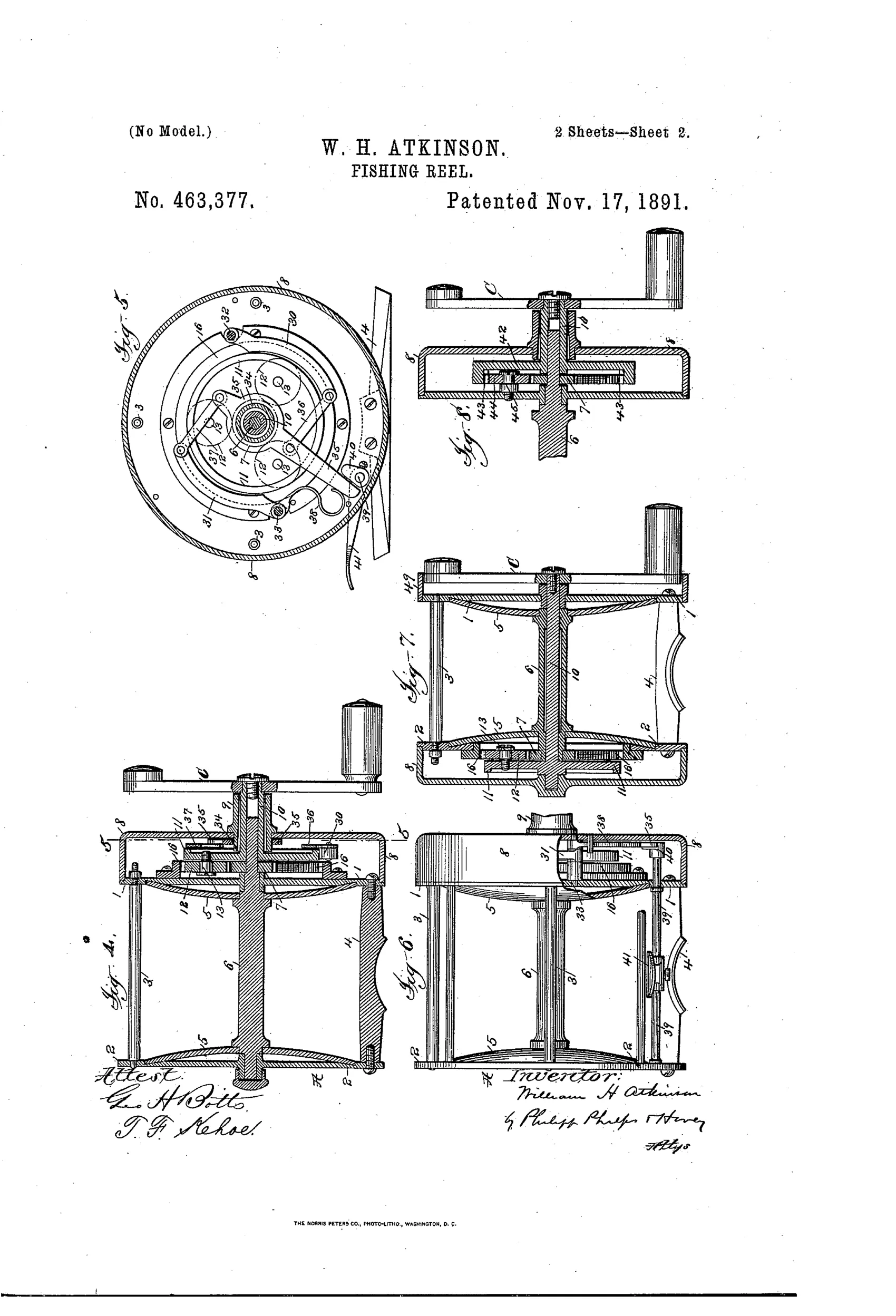
A crank-shaft mounted centrally in the cap carries one or more driving-gears that both rotate on their own axes and revolve bodily around the crank-shaft, meshing between the spool-shaft gear and a stationary interior gear. This planetary arrangement produces a high multiplication ratio in a compact space using few gears and bearings. A slide-locking mechanism can disengage the interior gear so the disk and gears lock together for single-action (non-multiplying) use, and a pivoted or spring-loaded brake-piece can be forced against the disk rim to check spool rotation. Alternate versions relocate the gearing to the opposite end of the reel or use a fixed interior gear secured to the head-plate with intermediate gears for a non-changeable multiplying reel.
↻ What was claimed
“In a fishing-reel, the combination, with the spool-shaft and its gear, of an interior gear, a crank and crank-shaft, one or more driving-gears carried by the crank-shaft and having movements of rotation on and revolution with the crank-shaft, said driving-gears being mounted between and engaging the spool-shaft gear and interior gear, means for locking the interior gear in a fixed position, and means for locking the interior gear to the crank-shaft, substantially as described.”
In plain English: The reel uses a crank-driven set of gears that both spin in place and orbit around a central shaft, meshing between the spool gear and a fixed ring gear, with a way to lock the ring gear stationary or lock it to the crank shaft.
↻ In the inventor’s words
“By this arrangement of gears I am able to obtain within a very small compass and without employing gears of large size a degree of multiplication in excess of that employed in fishing-reels as heretofore constructed.”— William H. Atkinson, from the specification
Paper patent — likely never produced
No Atkinson-marked reel or licensed production of this planetary design is documented, and the internal ring gear would have been costly to cut; a surviving specimen would change the call.
↻ More by William H. Atkinson
- FISHING-REEL ATTACHMENT. (1890)
↻ Commentary
Most multiplying reels of 1891 did the obvious thing: a big gear on the crank driving a small pinion on the spool shaft, the way the Kentucky watchmakers had done it since Snyder. Atkinson, working in Brooklyn — Julius vom Hofe's town — went a different way entirely. His crank carries small planet gears that both spin and orbit, meshing between the spool-shaft gear and a fixed internal ring gear. It's an epicyclic train, the same architecture that would later run hub gears on bicycles and automobile transmissions, packed into a reel end cap. His own claim is honest about the payoff: high multiplication in a small diameter without oversized gears.
The genuinely clever bit is the mode switch. Lock the ring gear to the housing and you get the multiplied drive; release it and lock it to the crank instead, and the whole train rotates as one lump — a single-action reel at the flick of a slide. Fig. 2 shows the crowded planetary cluster and the brake-piece bearing on the disk rim; Fig. 1 reveals how much machining lives in that head plate.
And that machining is the problem. Cutting an accurate internal ring gear in 1891 was expensive work, and the trade already got adequate multiplication from two cheap spur gears. Atkinson solved a problem the market had priced differently. It's a mechanically sound dead end — sophisticated, workable, and ahead of what anyone was willing to pay for.
Commentary by Claude, The Fishing Reel Patent Archive’s resident enthusiast