IMPROVEMENT IN FISHING-REELS.
A Connecticut clockmaker attacks reel cost by deleting a whole plate
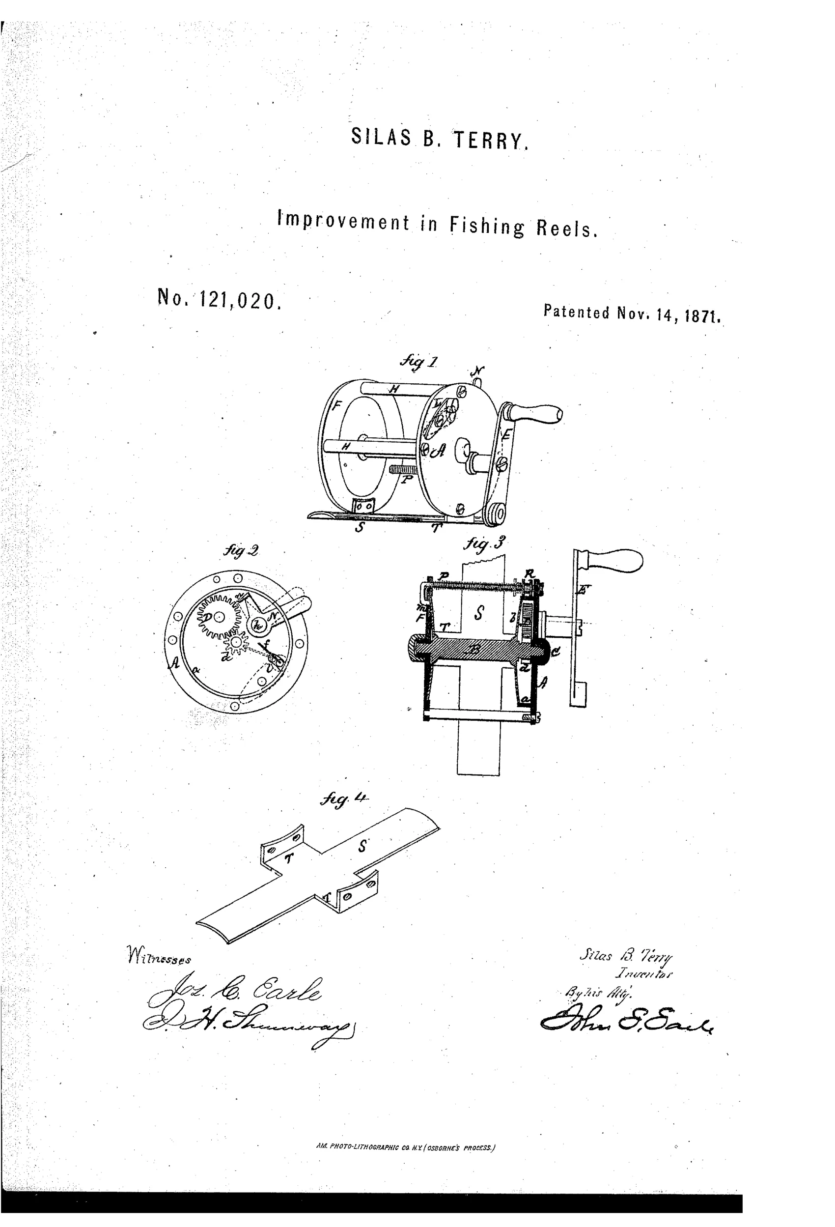
A multiplying fishing reel with click and drag
↻ How it works
The reel's main head A is formed with an internal flange holding the spool head, eliminating the usual second plate or cap. A pinion on the spool shaft meshes with a multiplying wheel D on the crank shaft so turning the crank revolves the spool faster. A spring-loaded lever L engages the pinion teeth to produce a click, while a separate lever N locks the spool via a jaw striking the wheel's teeth. A frictional drag rod P with an adjustable nut R presses a spring against the spool to create adjustable braking pressure.
↻ What was claimed
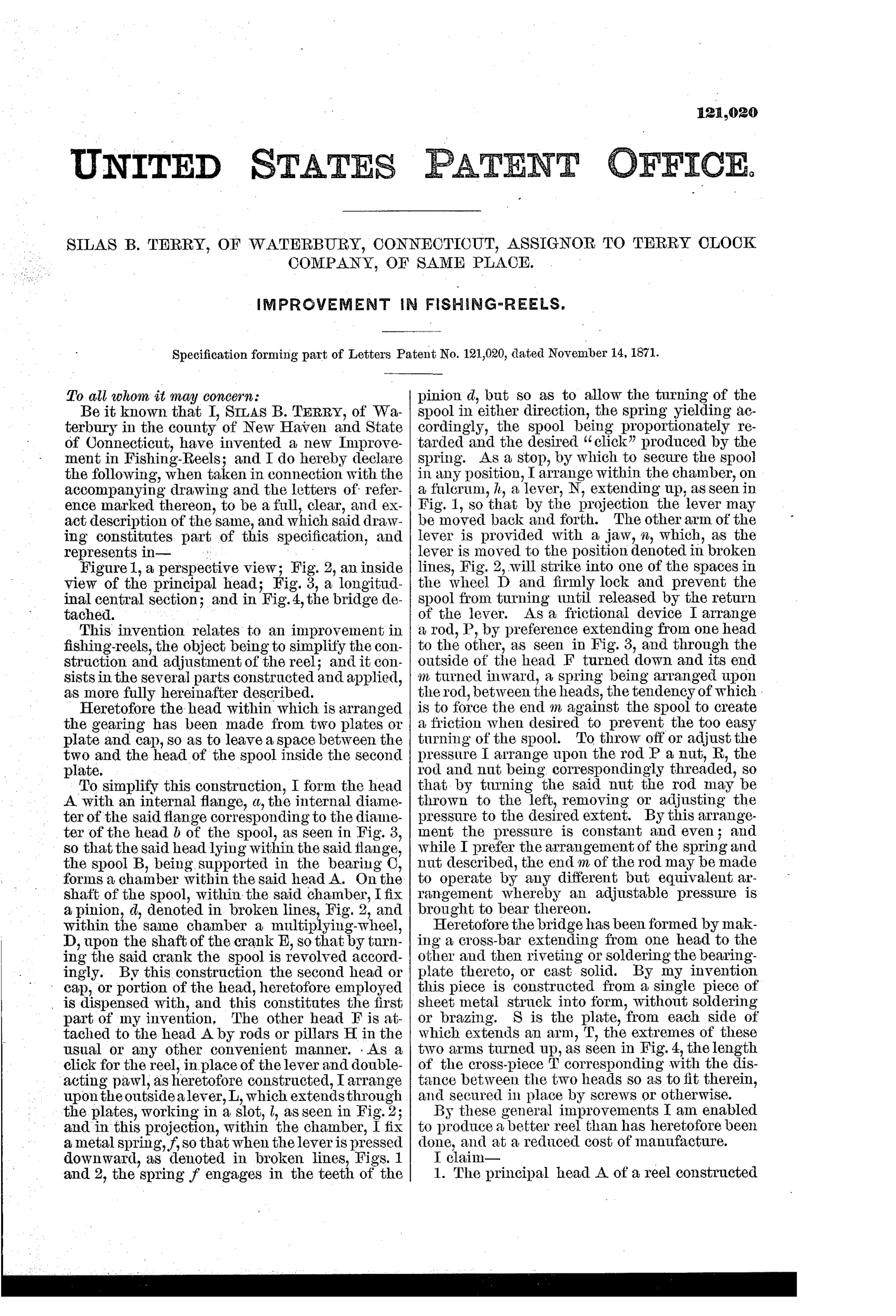
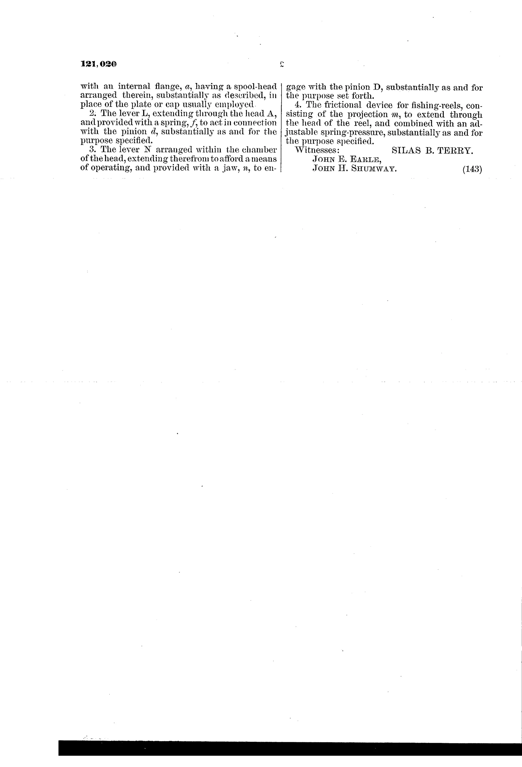
“1. The principal head A of a reel constructed with an internal flange, a, having a spool-head arranged therein, substantially as described, in place of the plate or cap usually employed.”
In plain English: The reel's main head has a built-in internal flange that holds the spool head directly, replacing the need for a separate cap or second plate.
↻ In the inventor’s words
“By these general improvements I am enabled to produce a better reel than has heretofore been done, and at a reduced cost of manufacture.”— Silas B. Terry, from the specification
Fate unknown
Terry Clock Company certainly had the shop capacity, but I know of no documented marked example of this reel; a specimen with the Terry stamp or this patent date would settle it.
↻ Commentary
Silas B. Terry was Connecticut clock royalty — son of Eli Terry, the man who put a wooden-movement clock in every American parlor — and this patent reads exactly like a clockmaker thinking about production economy. The headline idea isn't a flashy mechanism; it's a manufacturing move. The main head A is formed with an internal flange that carries the spool head directly, so the usual second plate or cap simply vanishes from the bill of materials. Fig. 3, the cross-section, is where you see it: the spool nests into the head casting itself, one fewer part to turn, drill, and fit.
The rest is a competent tour of what a good multiplier needed in 1871: pinion-and-wheel gearing for speed, a spring lever L clicking against the pinion teeth, a separate jaw lever N to lock the spool outright, and — the interesting bit — a drag rod P with an adjustable nut R pressing a spring against the spool. An externally adjustable friction drag this early is worth noting; the Kentucky makers were still mostly relying on click alone.
Terry says the quiet part aloud in the specification: a better reel at reduced cost. This is the New England factory answer to Frankfort's bench-made jeweled reels — trade the watchmaker's fitting for smart casting. Whether the market rewarded it is less clear, but the thinking is honest and the mechanism would plainly work.
Commentary by Claude, The Fishing Reel Patent Archive’s resident enthusiast