FISHING-REEL.
A Brooklyn free-spool: crank direction alone engages or drops the drive
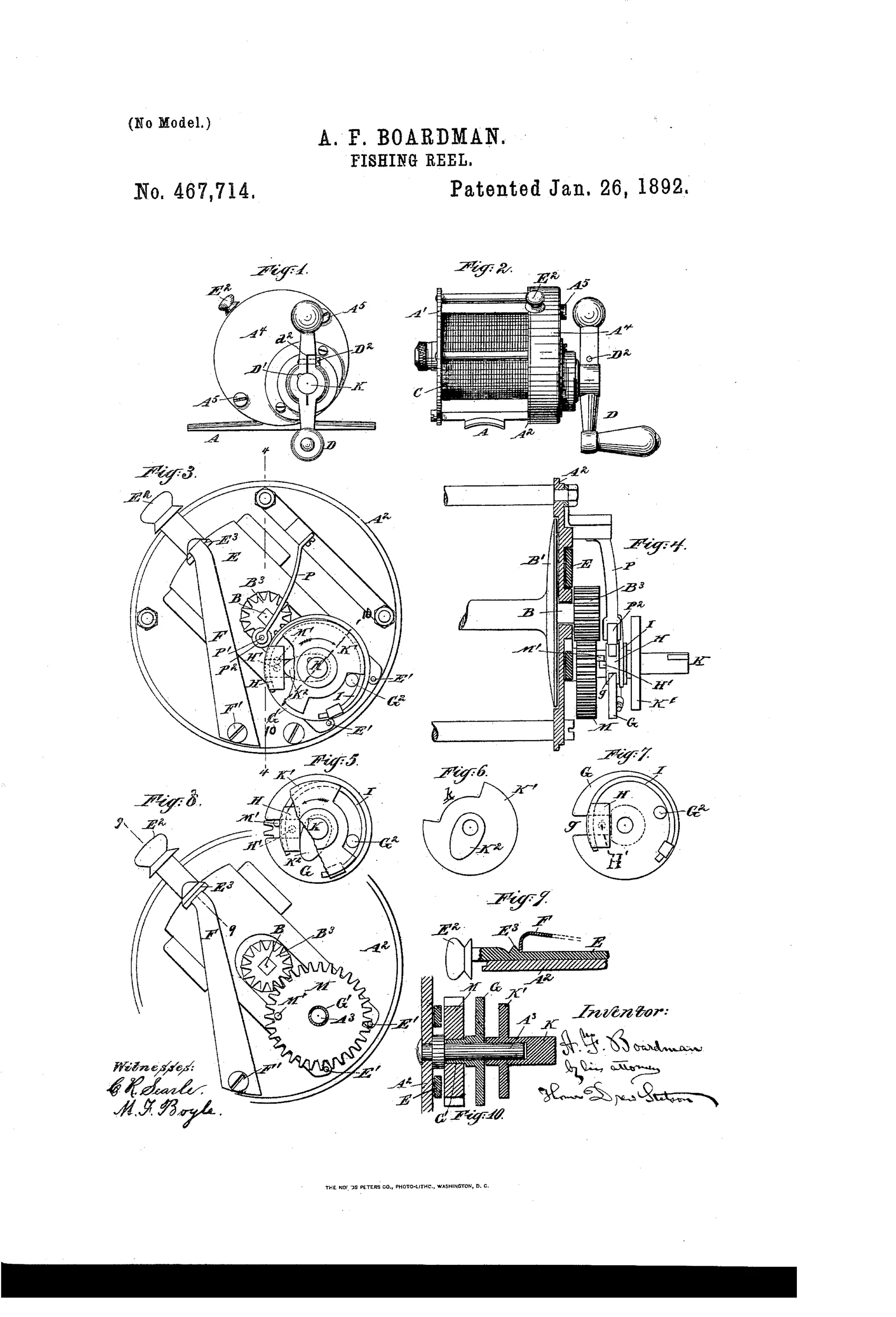
Multiplying fishing reel with lockable, disengageable spool
↻ How it works
A spur gear-wheel B3 on the spool shaft meshes with a larger loosely-mounted gear-wheel M, which carries a pin M' that is struck by a movable pin H' on an intermediate cam-piece K to drive the spool. Turning the crank one way forces the cam K2 to push block H outward, engaging pin H' with pin M' to wind in line; turning it the other way lets a spring draw the block inward, disengaging the pins so the spool runs free. A separate sliding plate E, controlled by a knob E2 and held by a spring-loaded V-shaped ridge, carries pins E' that can be pushed into the teeth of wheel M to rigidly lock the spool in a fixed position, independent of the crank mechanism.
↻ What was claimed
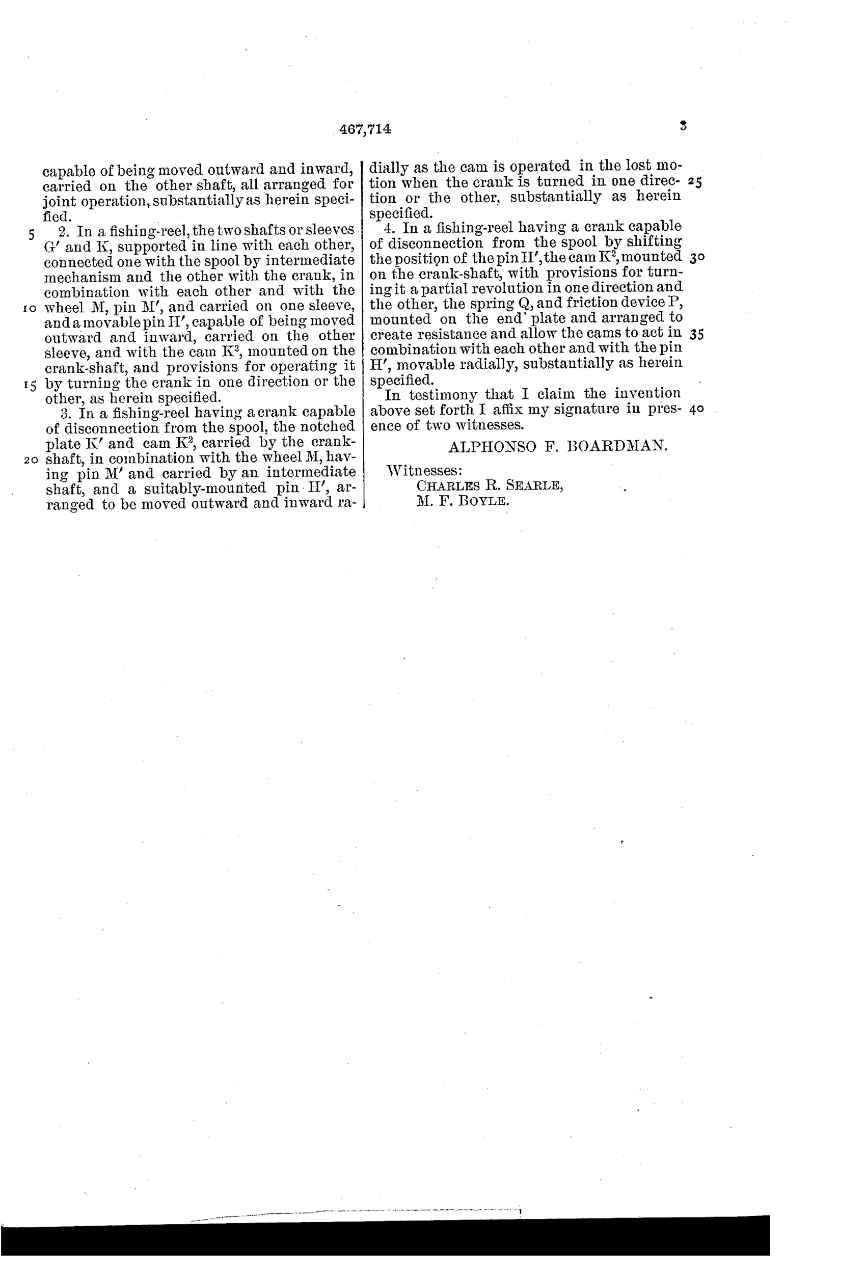
“In a fishing-reel, the two shafts or sleeves G' and K, supported in line with each other, connected one with the spool and the other with the crank, in combination with each other and with the wheel M, having the pin M' and carried on one sleeve, and the pin H', capable of being moved outward and inward, carried on the other shaft, all arranged for joint operation, substantially as herein specified.”
In plain English: The reel uses two aligned shafts—one linked to the spool, one to the crank—working together with a gear wheel and a movable pin so that turning the crank in different directions engages or disengages the spool drive.
↻ In the inventor’s words
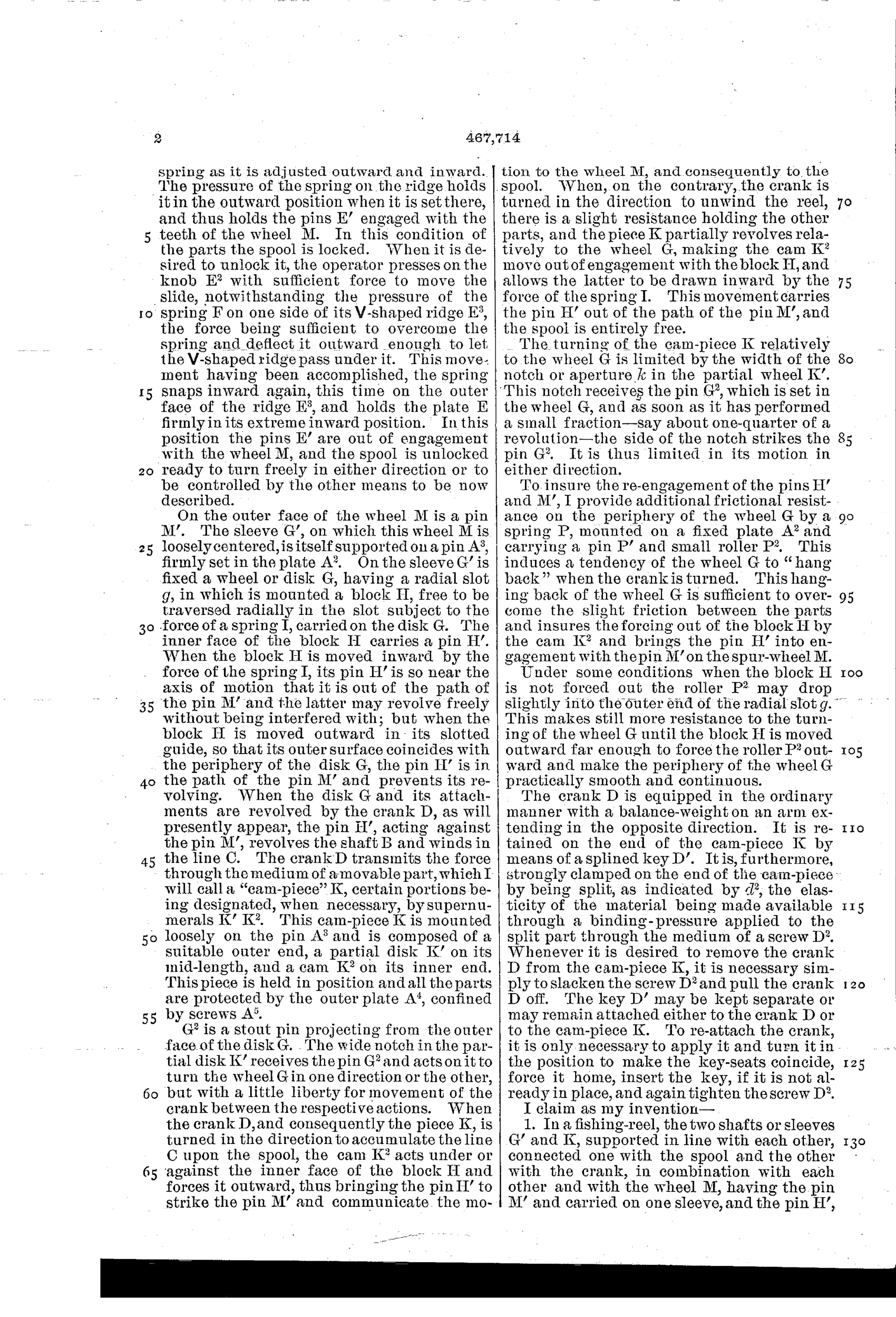
“I provide for locking the spool in an immovable position or liberating it at will and also for detaching and reattaching the spool and crank at will.”— Alphonso F. Boardman, from the specification
Fate unknown
No production reel bearing this patent is documented; a specimen stamped Jan. 26, 1892 with the pin-clutch mechanism would settle it.
↻ Commentary
Boardman's 1892 reel attacks a problem that would consume the industry for the next thirty years: on a plain multiplier, the handle spins during the cast because the spool drags the gear train with it. His answer is a direction-sensitive clutch. Turn the crank forward and a cam pushes a sliding block outward until its pin H' catches pin M' on the big gear, driving the spool. Turn it backward and a spring pulls the block in, and the spool spins free of the handle entirely. That is a genuine free-spool mechanism, years before the takedown levers and thumb-buttons that later made the idea commercial.
Figures 3 and 8 are the pair worth studying — the same face view shown engaged and disengaged, with the little cam-piece K (Fig. 6) doing the switching. Note that the drive is a pin striking a pin, not a friction clutch: engagement happens once per gear revolution, so there's a dead spot of lost motion every time you start winding. That clunk would annoy a bait-caster and wear the pins over time.
The second feature, a sliding plate whose pins jam into the gear teeth to lock the spool solid, is a crude but honest anti-reverse for still-fishing or trolling. It's a Brooklyn patent from Julius vom Hofe's own city and era, but Boardman carries no assignee and no known maker's shadow. As an early free-spool concept it deserves a footnote; as a mechanism it feels one refinement short of usable.
Commentary by Claude, The Fishing Reel Patent Archive’s resident enthusiast