IMPROVEMENT IN FISHING-LINE REELS.
Drag by squeeze: a set-screw pinches the spool between watchmaker's steel centers
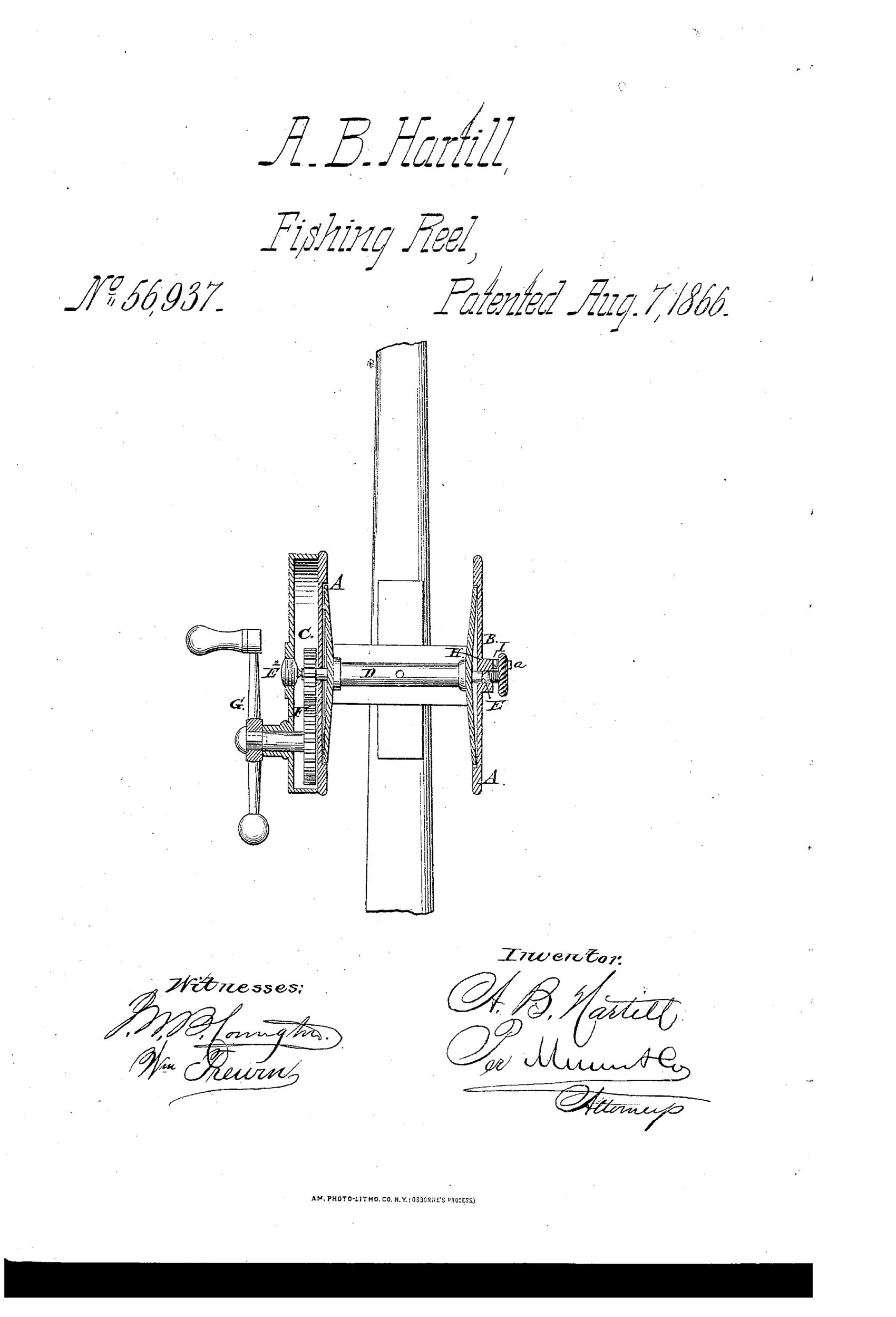
Fishing reel with adjustable drag mechanism
↻ How it works
The reel spool D is suspended between two head plates on hardened steel center pins, one fixed and one on a screw spindle. A gear train F with crank handle G turns the spool for winding line. The screw spindle H has a milled head J with a set-screw that abuts a fixed stud, allowing the operator to tighten the spool between its suspension points to create a drag, preventing the fish from running away with the line.
↻ What was claimed
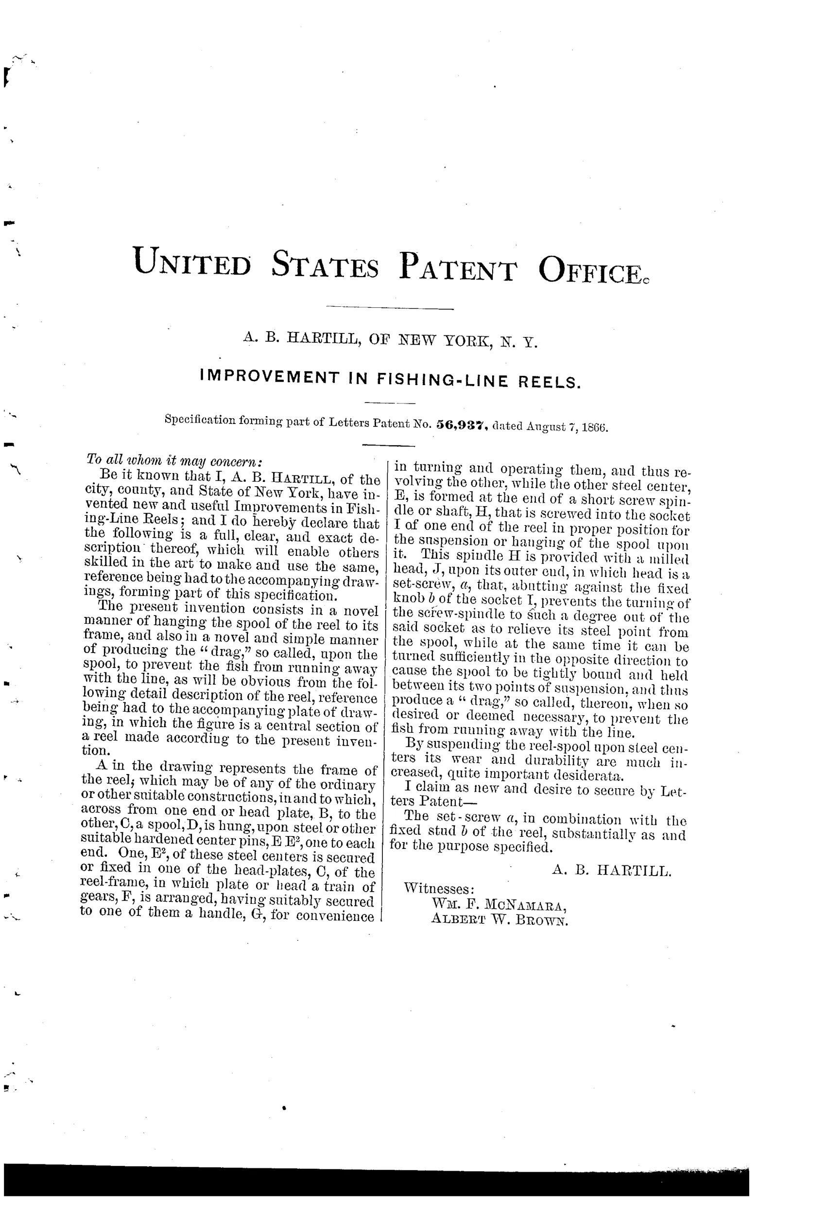
“The set-screw a, in combination with the fixed stud b of the reel, substantially as and for the purpose specified.”
In plain English: The invention claims a set-screw working against a fixed stud to adjust and create drag tension on the reel spool.
↻ In the inventor’s words
“By suspending the reel-spool upon steel centers its wear and durability are much increased, quite important desiderata.”— A. B. Hartill, from the specification
Fate unknown
No documented production example under Hartill's name is known to me; a marked specimen or trade listing would settle it.
↻ Commentary
Hartill's 1866 patent is an early American answer to a question that would dominate reel design for the next half-century: how do you keep a hooked fish from stripping line freely without simply grabbing the spool with your thumb? His solution is elegantly crude. The spool rides between two hardened steel center pins, like the balance wheel of a watch — and one of those pins sits on a threaded spindle. Turn the milled head J and you literally squeeze the spool tighter between its bearing points, adding friction. A set-screw against a fixed stud locks the adjustment so it doesn't creep under load.
The watchmaking pedigree is unmistakable, and it echoes what Snyder and the Meeks had been doing in Kentucky since the 1830s: pivoted steel centers for low friction and long wear. Hartill's own text calls the durability gain 'quite important desiderata,' which tells you where his head was — bearing quality first, drag as a bonus.
The weakness is also plain. Drag applied by axial compression at the pivot points concentrates all the braking force on two tiny steel contact patches. It would work for light checking, but a hard-running fish would either gall the centers or demand so much compression the spool binds. Later drag designs moved the friction to washers and larger surfaces for exactly this reason. Still, as an 1866 attempt at an adjustable, lockable drag, it's a genuinely thoughtful dead end.
Commentary by Claude, The Fishing Reel Patent Archive’s resident enthusiast