FISHING-REEL
A reel built into the rod itself, with a sliding gear for free-spool casting
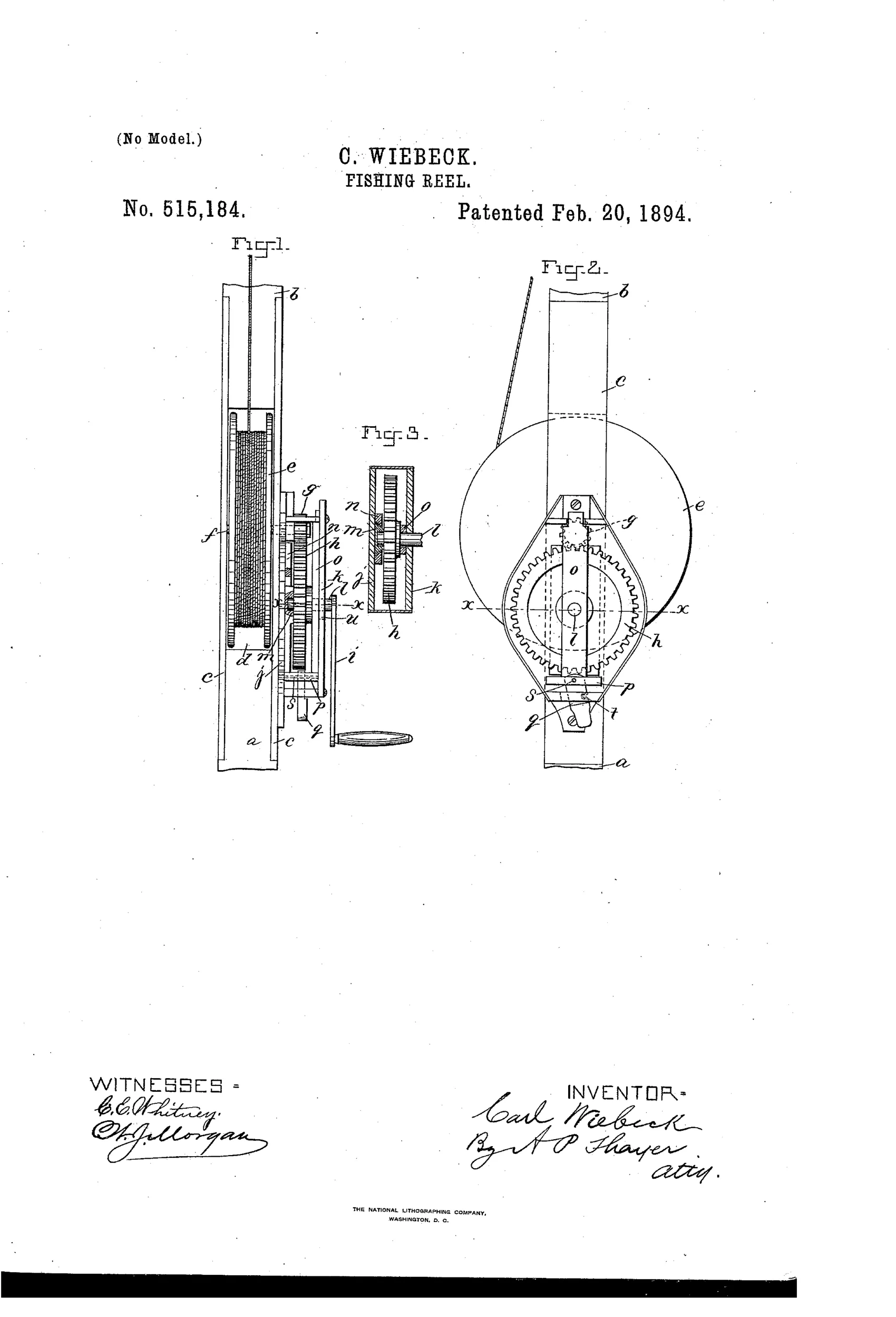
Fishing rod reel with disengaging gear drive
↻ How it works
The reel is mounted between metal plates set into the rod, with its pivot shaft carrying a toothed pinion projecting through one side plate. A separate toothed master wheel, mounted on a shaft in slide ways radial to the pinion, meshes with the pinion to drive the reel via a crank. A cross head connected to the master wheel's bearing and bar can be shifted by a catch-pawl to move the master wheel into or out of gear with the pinion, letting the reel spin freely for casting or engaging it again to wind the line.
↻ What was claimed
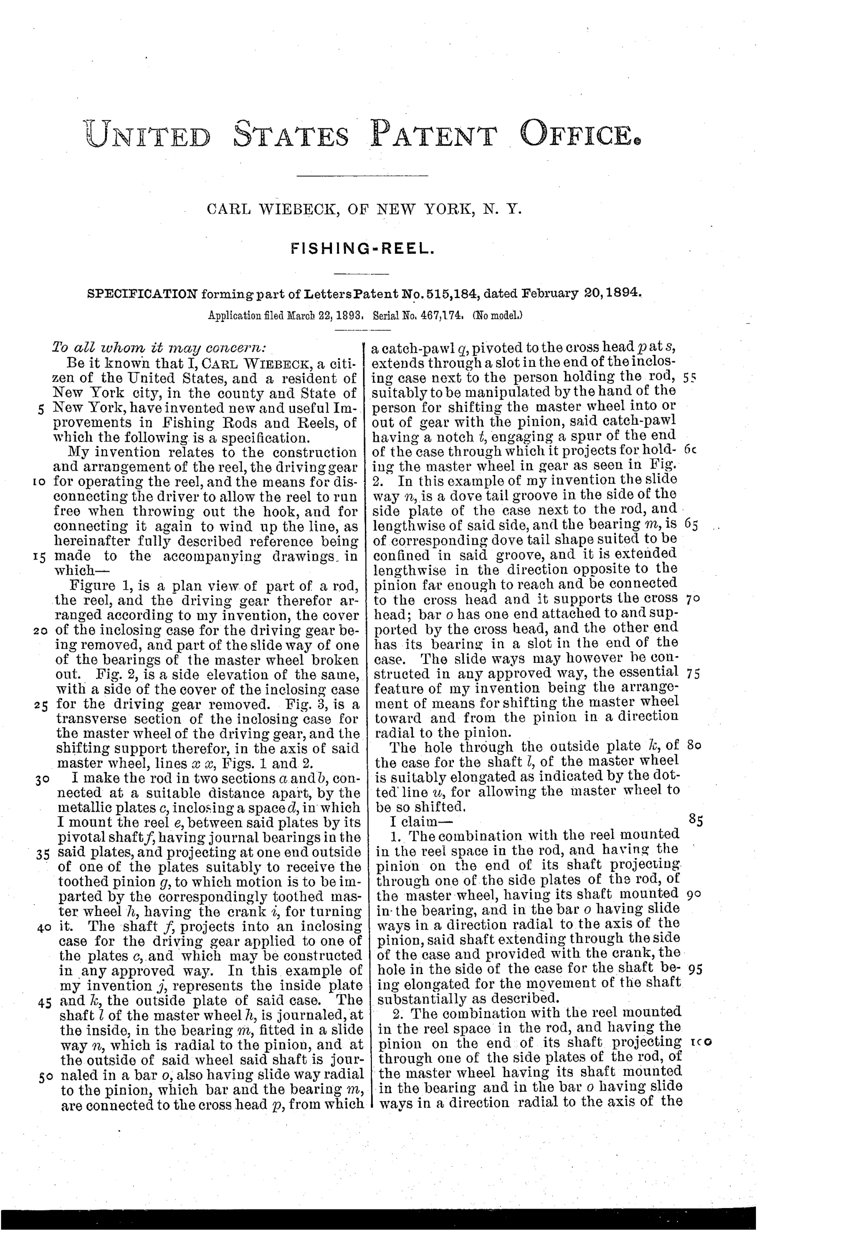
“The combination with the reel mounted in the reel space in the rod, and having the pinion on the end of its shaft projecting through one of the side plates of the rod, of the master wheel, having its shaft mounted in the bearing, and in the bar o having slide ways in a direction radial to the axis of the pinion, said shaft extending through the side of the case and provided with the crank, the hole in the side of the case for the shaft being elongated for the movement of the shaft substantially as described.”
In plain English: A fishing reel with a pinion gear on its shaft, combined with a crank-driven master wheel that slides radially toward or away from the pinion to engage or disengage the drive, through an elongated slot in the case.
↻ In the inventor’s words
“My invention relates to the construction and arrangement of the reel, the driving gear for operating the reel, and the means for disconnecting the driver to allow the reel to run free when throwing out the hook, and for connecting it again to wind up the line, as hereinafter fully described reference being made to the accompanying drawings.”— Carl Wiebeck, from the specification
Paper patent — likely never produced
In-rod reels of this type have no known commercial lineage and no documented Wiebeck production example; the design's integration with the rod made manufacture and sale impractical.
↻ Commentary
Wiebeck's patent tackles two ideas at once, and either one alone would have been ambitious. First, the reel doesn't clamp onto the rod — it lives inside it, mounted between metal plates set into a cutout, with the line running up through the hollow butt. Fig. 1 shows this clearly: the spool sits in a recess in the rod blank, and the line (marked f) travels internally. Second, and more interesting for the mechanism-minded, is the drive: the crank doesn't turn the spool directly. It turns a large master wheel whose shaft rides in radial slide ways, so a pawl can shove the whole wheel out of mesh with the spool pinion. Slide it back and you're winding; slide it out and the spool spins free for the cast.
That's a genuine free-spool concept in 1894, decades before free-spool became a standard casting-reel feature. The trouble is everything around it. The elongated slot in the case for the crank shaft is a dirt and water invitation, gear teeth engaging under a shove tend to clash unless aligned, and an in-rod reel means the rod and reel live or die together — no swapping, awkward repairs, and a weakened rod section right where casting stress concentrates.
It sits as a dead-end branch: the free-spool instinct was right, but the industry solved it with sliding pinions inside conventional reel frames, not with reels buried in the rod.
Commentary by Claude, The Fishing Reel Patent Archive’s resident enthusiast