GOVERNOR FOR MECHANICAL POWERS
A centrifugal friction brake in 1883 — the anti-backlash idea before reels needed it
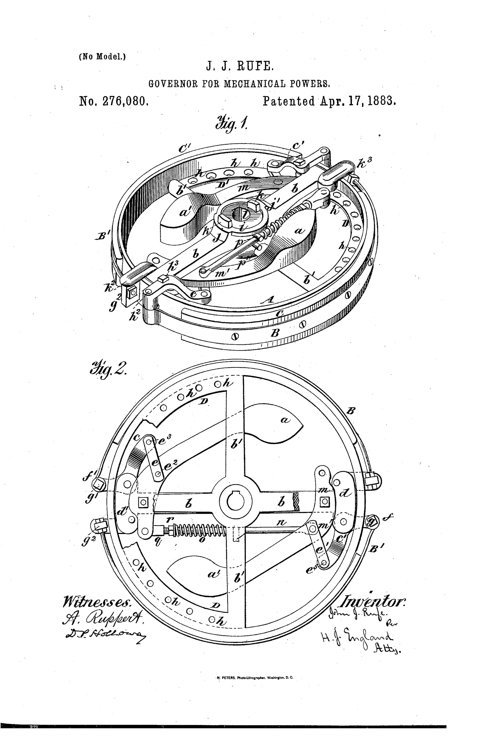
Centrifugal friction-band speed governor for machinery
↻ How it works
A spider or cross-arm keyed to a drive-shaft carries two weighted swinging levers (arms a and a') pivoted near the outer ends of the spider. As speed increases, centrifugal force throws the weighted arms outward, which via rock-arms and connecting-rods pulls clamping friction bands tight against the inner face of a surrounding wheel. This friction between the bands and the wheel slows the wheel, checking excess speed. A coiled spring and adjustable nut on the connecting rod counteract the outward pull of the weights and allow the desired regulated speed to be set.
↻ What was claimed
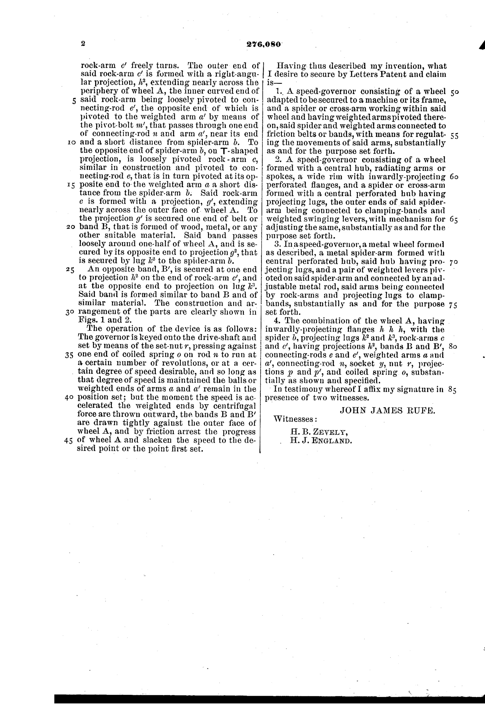
“A speed-governor consisting of a wheel adapted to be secured to a machine or its frame, and a spider or cross-arm working within said wheel and having weighted arms pivoted thereon, said spider and weighted arms connected to friction belts or bands, with means for regulating the movements of said arms, substantially as and for the purpose set forth.”
In plain English: A governor made of a wheel fixed to a machine, with a spider inside it holding weighted arms connected to friction bands, plus adjustable means to control those arms' movement.
↻ In the inventor’s words
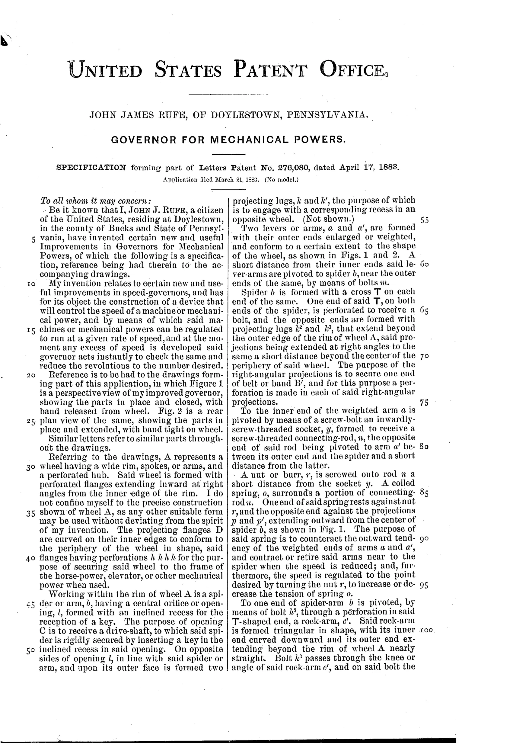
“The governor is keyed onto the drive-shaft and set by means of the set-nut r, pressing against one end of coiled spring o on rod n to run at a certain number of revolutions, or at a certain degree of speed desirable, and so long as that degree of speed is maintained the balls or weighted ends of arms a and a' remain in the position set; but the moment the speed is accelerated the weighted ends by centrifugal force are thrown outward, the bands B and B' are drawn tightly against the outer face of wheel A, and by friction arrest the progress of wheel A and slacken the speed to the desired point or the point first set.”— John James Rufe, from the specification
Fate unknown
No production example of Rufe's governor is documented; a surviving marked unit or trade-catalog listing would settle it.
↻ Commentary
Strictly speaking, this isn't a fishing reel at all. Rufe filed it as a governor for machinery: a spider keyed to a drive shaft carries two weighted swinging arms, and when the shaft spins too fast, centrifugal force throws the weights outward, pulling friction bands tight against the inside of a surrounding wheel and dragging the speed back down. A coiled spring and set-nut on the connecting rod let you dial in the speed at which the brake engages. It's a self-regulating, speed-proportional friction brake — no operator required.
That description should sound familiar to anyone who has followed the anti-backlash obsession of 1900-1920. The great problem of the casting reel is that the spool keeps spinning after the lure slows, overrunning the line into a bird's nest. The eventual answers — centrifugal brake blocks flying outward against a ring inside the end plate — are this exact mechanism, shrunk to fit under a thumb. Rufe's version has it all: the pivoted weights, the adjustable spring preload, the friction surface waiting for the overspeed.
The drawing is worth a careful look. Fig. 1 shows the bands released; Fig. 2 shows them drawn tight — the two states of every centrifugal brake since. Whether any machine shop ever built one at industrial scale, I can't say. But as a mechanical ancestor of the backlash-free reel, it's a genuinely instructive piece of paper, filed and issued in under a month.
Commentary by Claude, The Fishing Reel Patent Archive’s resident enthusiast