FISHING-REEL.
A clockwork mainspring inside a fishing reel, complete with planetary gearing
Spring-driven fishing reel with planetary gearing and brake
↻ How it works
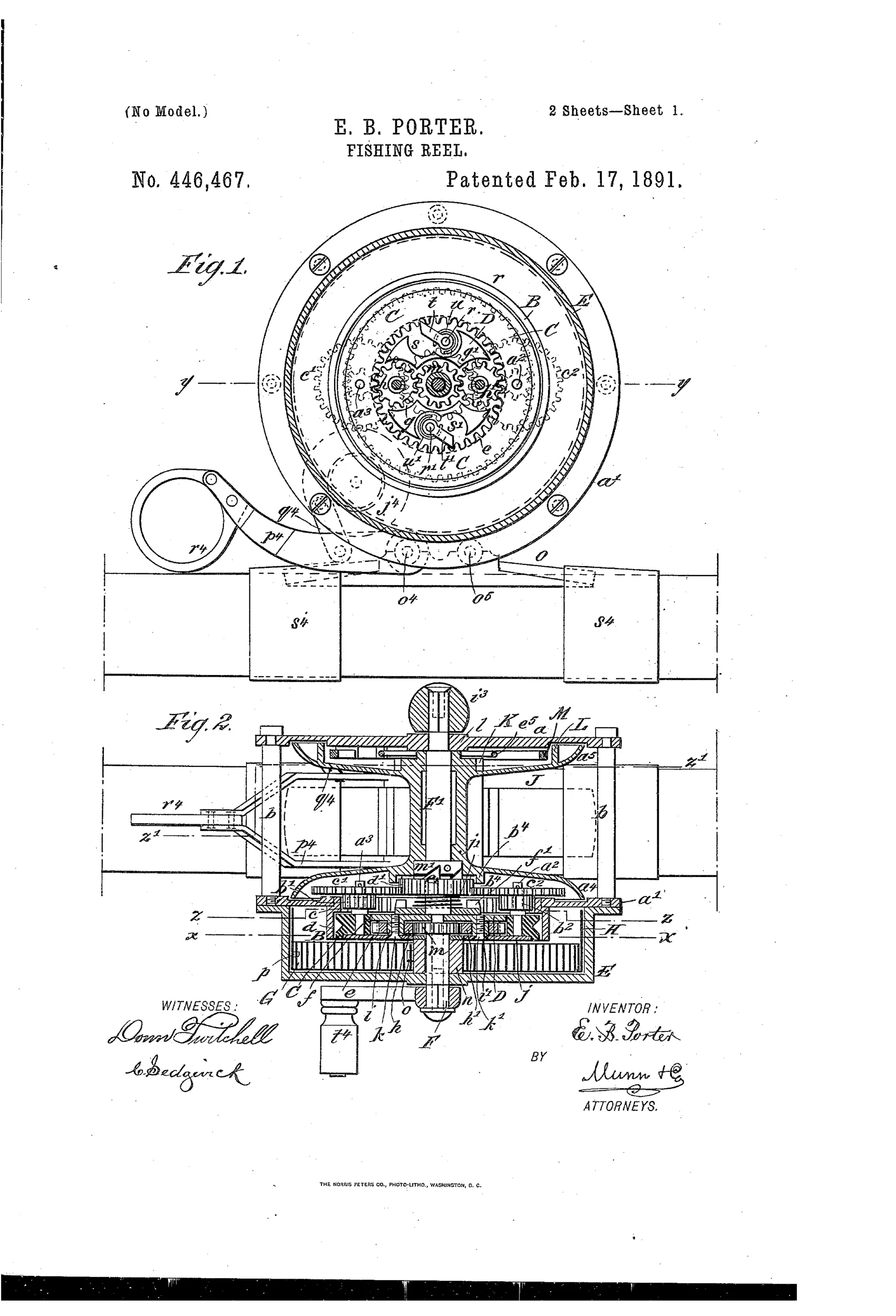
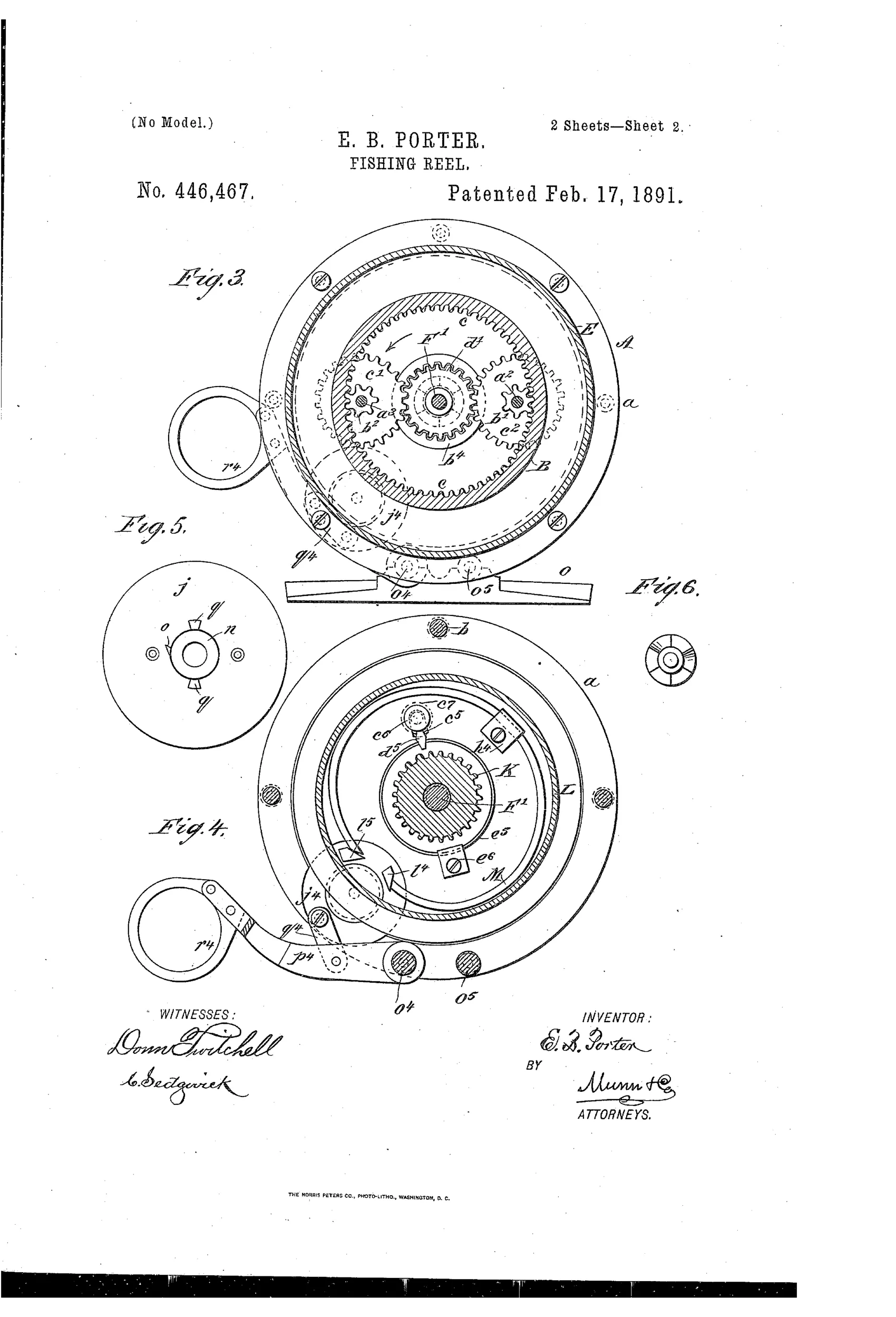
A hand crank turns a shaft and sleeve pinion which drives spur wheels engaging internal cogs of a geared ring, winding a volute spring housed in a drag-spring hub. The spring and reel are connected through intermediate planetary gearing so that turning the crank simultaneously winds the spring and turns the reel, the reel yielding when resistance exceeds the spring's tension. A spring-pressed pinion with beveled teeth can be disengaged from a toothed rim on the reel by turning a milled head, freeing the reel to pay out line without resistance. A separate C-shaped brake spring, expanded by a cam ring operated through a forked lever and link, bears on a brake-rim to retard the reel, while a diamond-shaped click engaging a spur-wheel gives an audible alarm and limits sudden overruns.
↻ What was claimed
“In a fishing-reel, the combination of the shaft F', the reel J, loosely mounted on the shaft, the sleeve F on the shaft outside of the reel, the pinion m on the inner end of the sleeve, a handle on the outer end of the sleeve, a spring, and gearing between the spring and reel and operated by the pinion of the sleeve, substantially as described.”
In plain English: The reel combines a shaft, a freely rotating reel on the shaft, a sleeve with a crank handle and drive pinion, and a spring connected to the reel through gearing so that the crank both winds the spring and turns the reel.
↻ In the inventor’s words
“The operation of winding the spring and of revolving the reel may continue simultaneously, or the spring may be wound and the reel may be operated by the power stored in the spring.”— Elbert B. Porter, from the specification
Fate unknown
No production example of this Porter design is documented in the collecting literature; a marked specimen would settle it.
↻ More by Elbert B. Porter
- FISHING-REEL (1893)
↻ Commentary
Elbert Porter of Penn Yan wanted the crank to do double duty: every turn of the handle winds a volute spring while it turns the spool, so that stored energy can take over the retrieve or, more subtly, act as a yielding drag. When a fish pulls harder than the spring's tension, the reel gives way against the spring instead of against the angler's knuckles. That is a genuinely interesting idea — a shock absorber built into the drivetrain — and it anticipates in spirit what later spring-tension drags tried to do more simply.
The drawing shows how much machinery the idea demanded. Fig. 1 is nearly all gearing: an internally toothed ring, planet wheels, a clutch plate to couple the spring, plus a separate C-spring brake expanded by a cam ring and forked lever, and a diamond-shaped click for the audible alarm. That is watchmaker's work — appropriate for 1891, when Kentucky watchmakers still set the standard — but it is also weight, cost, and a dozen points of failure sitting between the handle and the line.
Automatic and spring-driven reels did find a market, mostly in fly fishing where Yawman & Erbe's simpler design won out. Porter's hybrid, where the spring shares the drivetrain with the crank through planetary gears, sits in the dead-end branch of that family: clever, coherent on paper, and almost certainly too elaborate to build at a price anglers would pay.
Commentary by Claude, The Fishing Reel Patent Archive’s resident enthusiast