FISHING-REEL
A clockwork reel that winds a spring while you crank, keeping the line taut
Spring-driven multiplying fishing reel with clutch and brake
↻ How it works
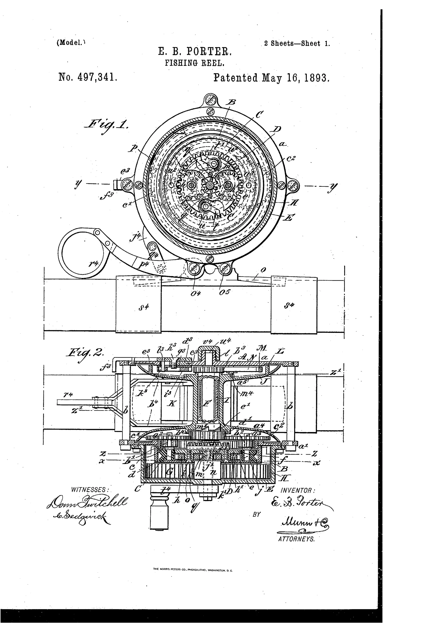
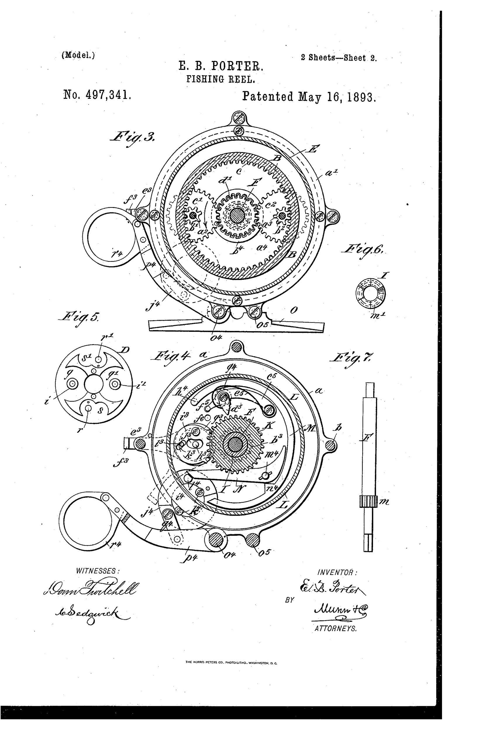
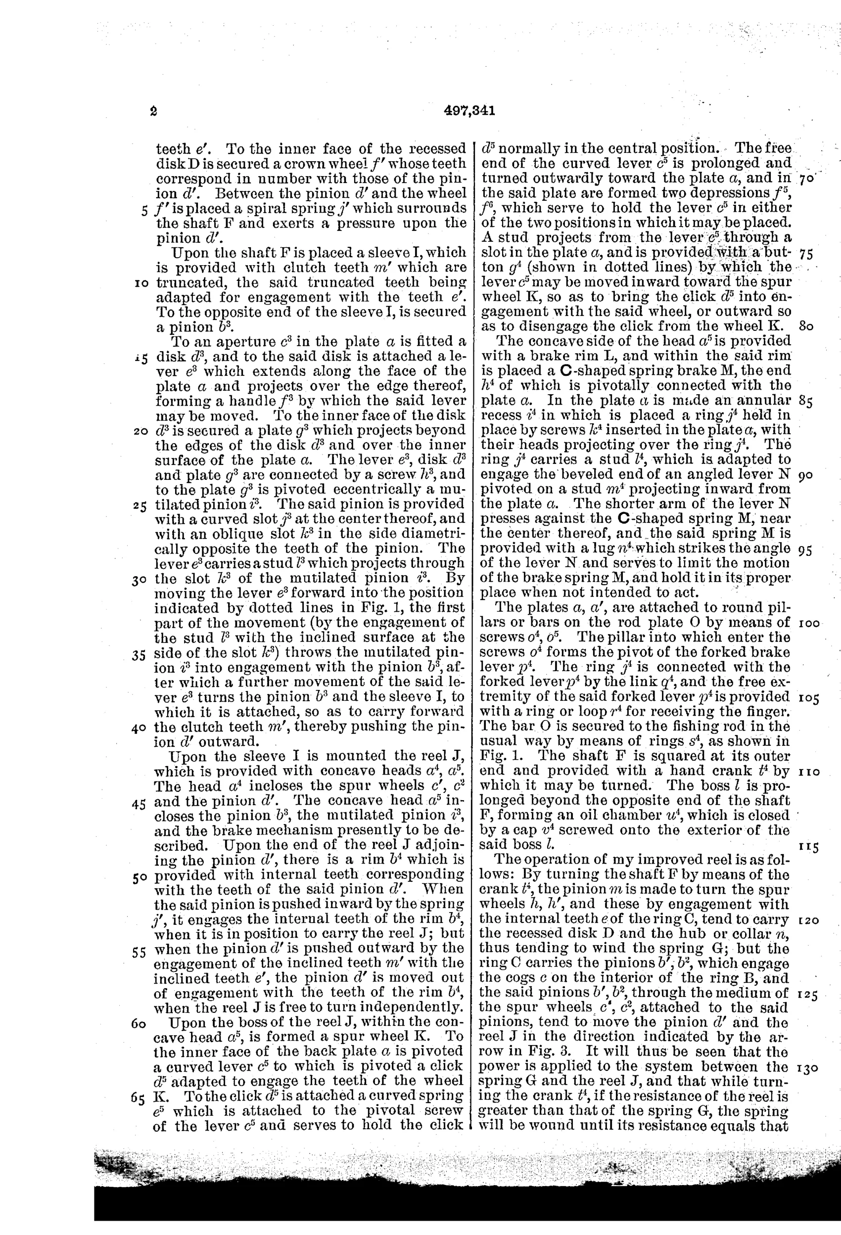
A crank turns a shaft through planetary gearing that simultaneously winds a volute spring and drives the reel spool, so the spring maintains continual tension on the line. A sliding pinion with inclined clutch teeth engages or disengages the spool from the drive train, allowing the line to pay out freely when a fish strikes. A pawl-and-click mechanism engages a spur wheel on the reel head to retard its motion and sound an alarm when the hook is taken, while a C-shaped brake spring pressing on a brake rim provides additional adjustable drag.
↻ What was claimed
“1. In a fishing reel, the combination, with a shaft and a reel mounted on one end thereof, of a train of gearing on the shaft outside of the reel and engaging the same, a collar mounted loosely on the shaft adjacent to the train of gearing and having a connection therewith, and a spring having one end connected to said collar, substantially as and for the purpose set forth.”
In plain English: The reel combines a shaft-mounted gear train with a loose collar connected to a spring, so that turning the shaft winds the spring while driving the reel.
↻ In the inventor’s words
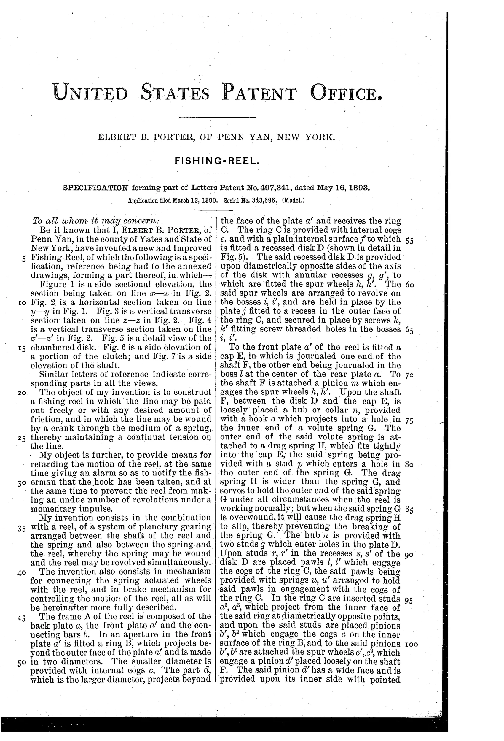
“The object of my invention is to construct a fishing reel in which the line may be paid out freely or with any desired amount of friction, and in which the line may be wound by a crank through the medium of a spring, thereby maintaining a continual tension on the line.”— Elbert B. Porter, from the specification
Fate unknown
No production example of Porter's reel is documented; a marked specimen or trade-catalog listing would settle it.
↻ More by Elbert B. Porter
- FISHING-REEL. (1891)
↻ Commentary
Porter's idea is a reel that behaves less like a winch and more like a watch. The crank doesn't drive the spool directly; it turns a shaft through planetary gearing that both winds a volute spring and rotates the spool, so the spring keeps continual tension on the line even when your hand pauses. Fig. 1's face-on view — that nest of spur wheels and pinions filling the entire head plate — looks more like a clock movement than any casting reel of the day, and the drawing's density is an honest confession of the design's complexity.
He layers on everything a fisherman might want: a sliding pinion with inclined clutch teeth so a striking fish can pull line without fighting the gearing, a pawl-and-click that doubles as a strike alarm, and a C-shaped brake spring on a rim for adjustable drag. Each piece is sensible on its own; together they're a lot of small parts to keep clean, dry, and adjusted on a riverbank.
The idea itself wasn't a dead end — Yawman & Erbe's spring-driven automatic fly reels were already on the market and would thrive for decades. Porter's version, with its clutch and dual braking, is more ambitious and more fragile-looking than what actually sold. It reads as an inventor's complete answer to a question the trade solved with fewer gears.
Commentary by Claude, The Fishing Reel Patent Archive’s resident enthusiast