FISHING-REEL
The whole reel slides sideways on the rod to brake its own spool
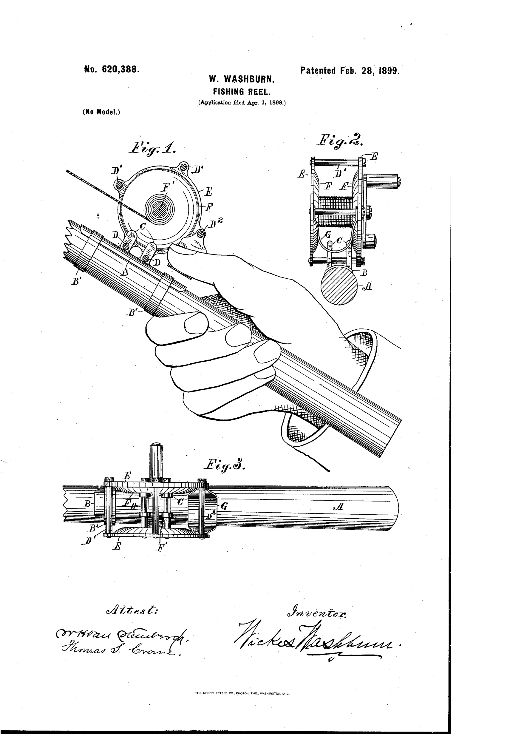
Fishing reel with lateral-shift friction brake
↻ How it works
The reel cage is mounted so it can shift slightly sideways along the pole on tie-rods fitted to lugs projecting from a foot-piece clamped to the rod. Pressing a loop or thumb-piece connected to the tie-rods shifts the cage laterally so a spool flange presses against the fixed lugs, creating drag to slow the spool. Because the tie-rods are slightly inclined toward one another, moving the cage one way jams the lugs on the rods to lock the spool entirely, while moving it the other way merely brakes it without locking. This lets the angler control line tension or fully lock the reel using only thumb pressure, without any separate braking mechanism.
↻ What was claimed
“The combination, with a fishing-reel having a cage with tie-rods, and spool journaled inside the cage, of a fishing-pole and means for holding the cage movable upon the pole, and a brake actuated by such movement of the cage to check or lock the rotation of the spool, substantially as herein set forth.”
In plain English: A fishing reel whose cage can slide slightly on the rod, and that sliding motion presses a brake against the spool to slow or lock it.
↻ In the inventor’s words
“The construction is exceedingly simple and effective and places the speed and tension of the line perfectly under the control of the fisherman, while it is incapable of derangement and requires no complicated and delicate attachments to operate as a brake.”— Wickes Washburn, from the specification
Fate unknown
Washburn is not a known reel maker and no production example is documented; a marked specimen with this sliding-cage mount would settle it.
↻ Commentary
Most inventors chasing drag control in the 1890s added something to the reel — a leaf spring, a screw-adjusted friction pad, a click pawl. Washburn did the opposite: he made the entire reel the brake lever. The cage rides on tie-rods fitted through lugs on the foot-piece, and a squeeze of the thumb-loop shifts the whole assembly sideways so a spool flange rubs against the fixed lugs. No added parts inside the reel at all.
The genuinely clever detail is easy to miss in Fig. 3: the tie-rods are slightly inclined toward one another. Shift the cage one direction and the lugs jam on the converging rods, locking the spool dead; shift it the other way and you get a proportional friction brake. Two functions — lock and drag — from one geometric trick, with no springs or ratchets to foul. His boast that it is 'incapable of derangement' is at least half-earned.
The trouble is what that freedom costs. A reel that must float laterally on its mount can never feel rock-solid, and every knock or twist of the hand becomes a potential brake application — including mid-cast, when you least want it. The trade never followed this path; it went instead toward internal drags and, soon after, the anti-backlash governors that consumed the next two decades. This is an ingenious dead end: a real solution to spool control, delivered through a mounting scheme anglers would not have trusted.
Commentary by Claude, The Fishing Reel Patent Archive’s resident enthusiast