AUTOMATIC FISHING-REEL.
A slip-clutch crank: the drag lives inside the handle, not the spool.
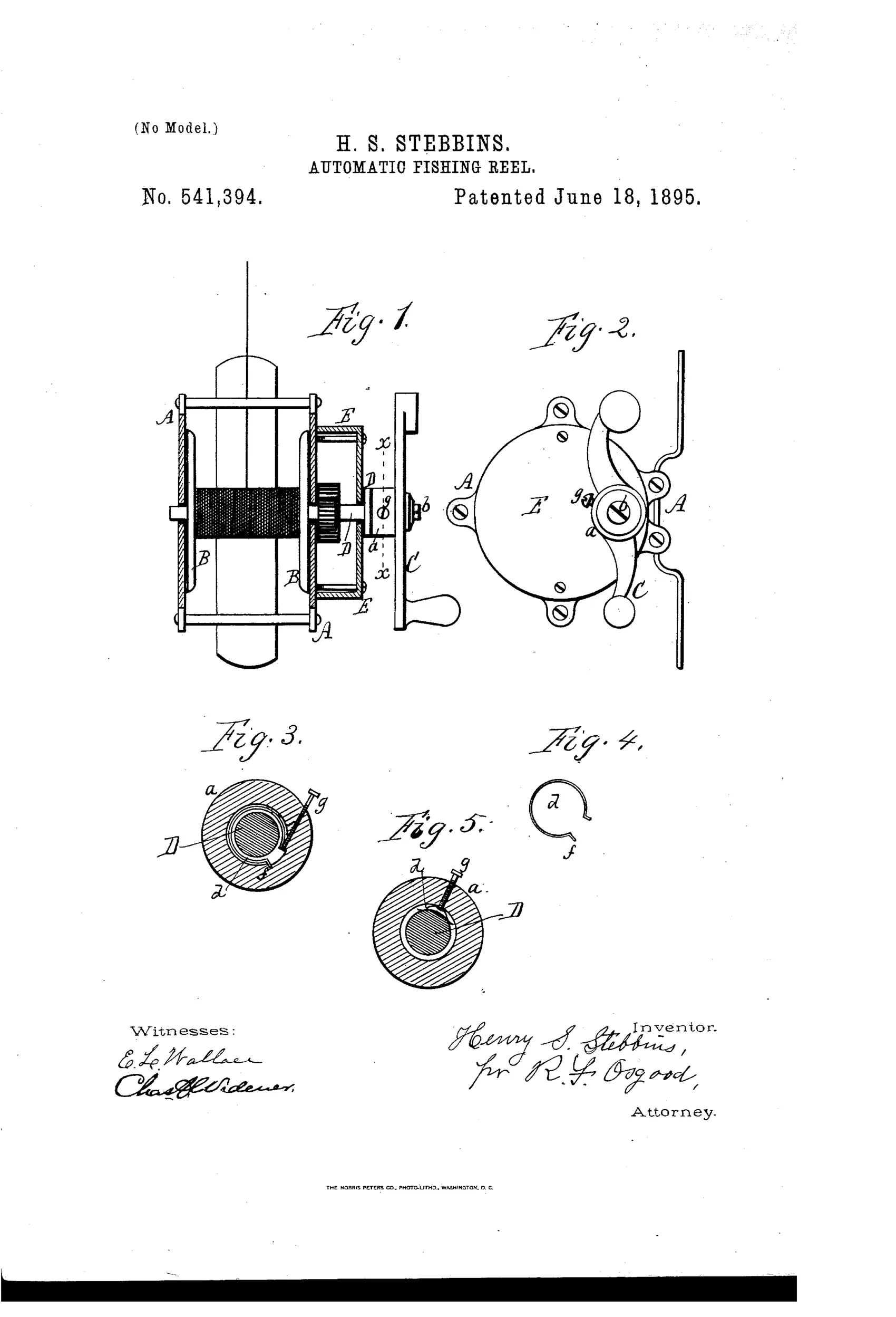
Friction-clutch crank mechanism for a fishing reel
↻ How it works
A winding spool turns within a stationary frame and is driven by a shaft connected to a crank. Instead of the crank being fixed to the shaft, its hub fits loosely on the shaft and holds a light friction spring pressed against the shaft by an adjustable set screw. When resistance on the spool is light, the spring's friction locks the crank to the shaft so both rotate together for normal winding, but when a fish pulls hard enough to exceed the spring's friction, the crank slips and rotates independently while the shaft and spool hold or pay out line without going slack. This dispenses with the coiled spring used in earlier automatic reels, giving a simpler, cheaper, and more compact multiplying reel controlled entirely by hand-adjustable friction.
↻ What was claimed
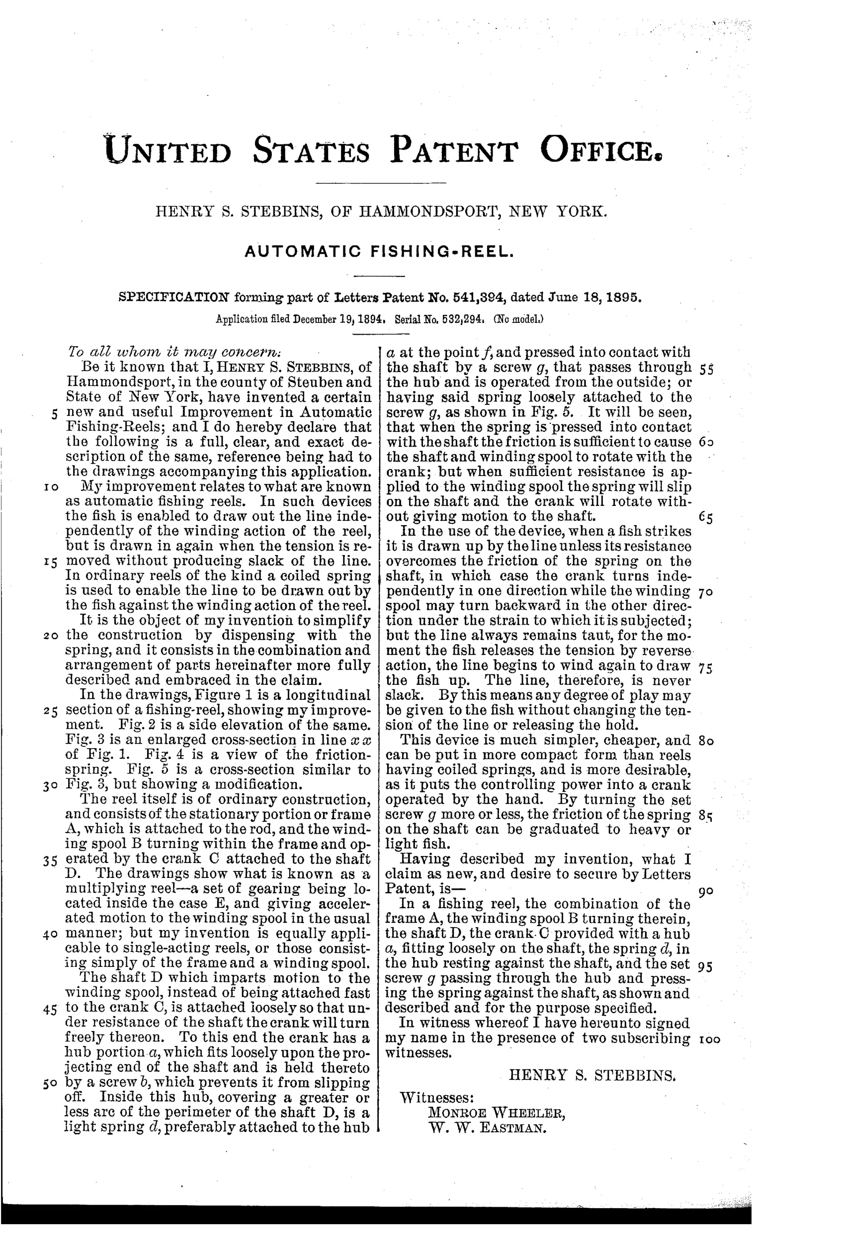
“In a fishing reel, the combination of the frame A, the winding spool B turning therein, the shaft D, the crank C provided with a hub a, fitting loosely on the shaft, the spring d, in the hub resting against the shaft, and the set screw g passing through the hub and pressing the spring against the shaft, as shown and described and for the purpose specified.”
In plain English: The reel combines a frame, a spool turning in it, a shaft, and a crank whose loose hub holds a friction spring pressed by an adjustable screw against the shaft, letting the crank slip when line tension is too great.
↻ In the inventor’s words
“The line, therefore, is never slack.”— Henry S. Stebbins, from the specification
Fate unknown
Stebbins is not a documented maker and no marked production reel is known to me; a surviving example stamped with this patent date would settle it.
↻ Commentary
Most drag mechanisms of this era brake the spool. Stebbins turns the problem inside out: his crank hub fits loosely on the shaft, gripping it only through a small friction spring tensioned by a set screw. Wind normally and the friction carries the crank and shaft together. Let a fish pull hard enough and the crank simply slips — the shaft turns backward under the crank while the angler's hand stays put. The line pays out under constant tension, which is why the patent's best line is also its whole argument: "The line, therefore, is never slack."
Figures 3 through 5 are where the idea actually lives. The reel itself in Figs. 1 and 2 is a conventional raised-pillar multiplier; the enlarged cross-sections show the little curved spring (Fig. 4) nested in the hub with the screw bearing down on it. That's the entire invention — maybe three parts and a threaded hole. Stebbins pitches it explicitly as a replacement for the coiled mainsprings of true automatic reels, which were bulky, expensive, and prone to failure. Calling it "automatic" is a stretch; it's really an adjustable slip drag in the handle.
The weakness is the one that dogs all small friction surfaces: a spring pressed against a smooth shaft gives a narrow, touchy adjustment range, and wear changes the setting. The industry ultimately put slipping drags on the spool or drive gear with larger friction faces. Still, this is an honest, cheap answer to a real problem, from a small-town inventor working the same puzzle the big Brooklyn shops were.
Commentary by Claude, The Fishing Reel Patent Archive’s resident enthusiast