Fishing-Reel
A crank that folds down and becomes its own line lock
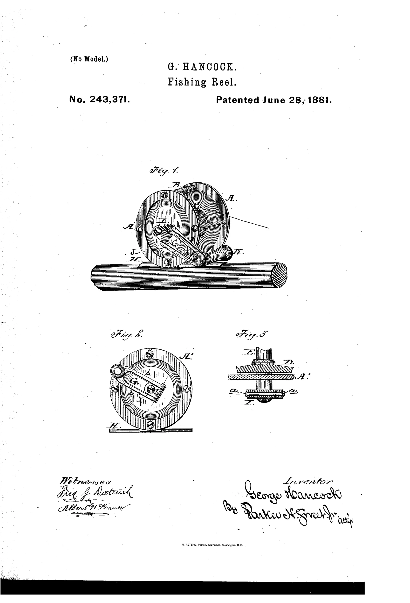
Fishing reel with pivoted stop-crank mechanism
↻ How it works
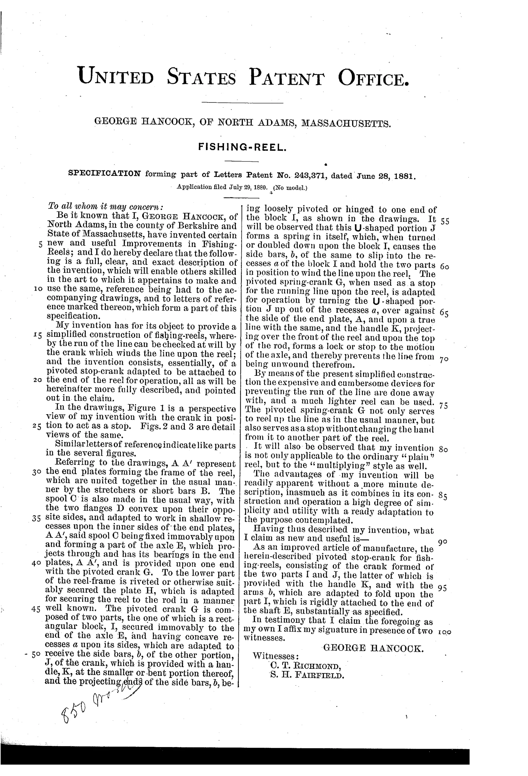
The reel has end plates A, A' joined by stretcher bars B, with a spool C fixed to an axle E that has bearings in the end plates. The axle terminates in a pivoted crank G composed of two parts: a rectangular block I rigidly attached to the axle end, and a U-shaped handle portion J with side bars b that fold into recesses a on block I. When the handle K is folded down and locked against the side of end plate A, it acts as a stop that prevents the axle from turning, thereby locking the line against unwinding without requiring a separate braking device.
↻ What was claimed
“As an improved article of manufacture, the herein-described pivoted stop-crank for fishing-reels, consisting of the crank formed of the two parts I and J, the latter of which is provided with the handle K, and with the arms b, which are adapted to fold upon the part I, which is rigidly attached to the end of the shaft E, substantially as specified.”
In plain English: A fishing reel crank made of two folding parts that can lock together to stop the reel's axle and prevent the line from unwinding.
↻ In the inventor’s words
“By means of the present simplified construction the expensive and cumbersome devices for preventing the run of the line are done away with, and a much lighter reel can be used.”— George Hancock, from the specification
Fate unknown
Hancock is not a known production maker and no marked example is documented; a surviving reel with this two-part folding crank would settle it.
↻ Commentary
Hancock's idea is disarmingly simple: instead of adding a click pawl or a sliding drag button, make the crank itself the brake. The crank here is built in two pieces — a rectangular block fixed to the axle end, and a U-shaped handle whose side arms fold down into recesses on the block. Fold the handle flat and hook it against the end plate, and the axle simply cannot turn. No spring, no ratchet, no extra parts to corrode or gum up. His own pitch is honest about the goal: doing away with 'expensive and cumbersome devices' so 'a much lighter reel can be used.'
Look closely at Fig. 2 and you can see the geometry — the folded handle bar lying across the plate face, bearing against the frame like a door latch. It works as an all-or-nothing lock, which is the design's weakness as well as its charm. A click mechanism lets a fish take line under resistance; Hancock's crank gives you only 'free' or 'stopped.' Set the lock with a fish on and something gives — probably the leader.
So this is a storage-and-transport feature dressed up as a running brake. Folding crank handles did become common on later reels for exactly that reason, which makes Hancock an early voice on a real idea, even if his framing of it as a substitute for the drag was a dead end. A tidy, workmanlike patent from a Massachusetts inventor working outside the Kentucky mainstream.
Commentary by Claude, The Fishing Reel Patent Archive’s resident enthusiast