FISHING-REEL.
Yawman & Erbe's spring-driven automatic — the fly reel that winds itself
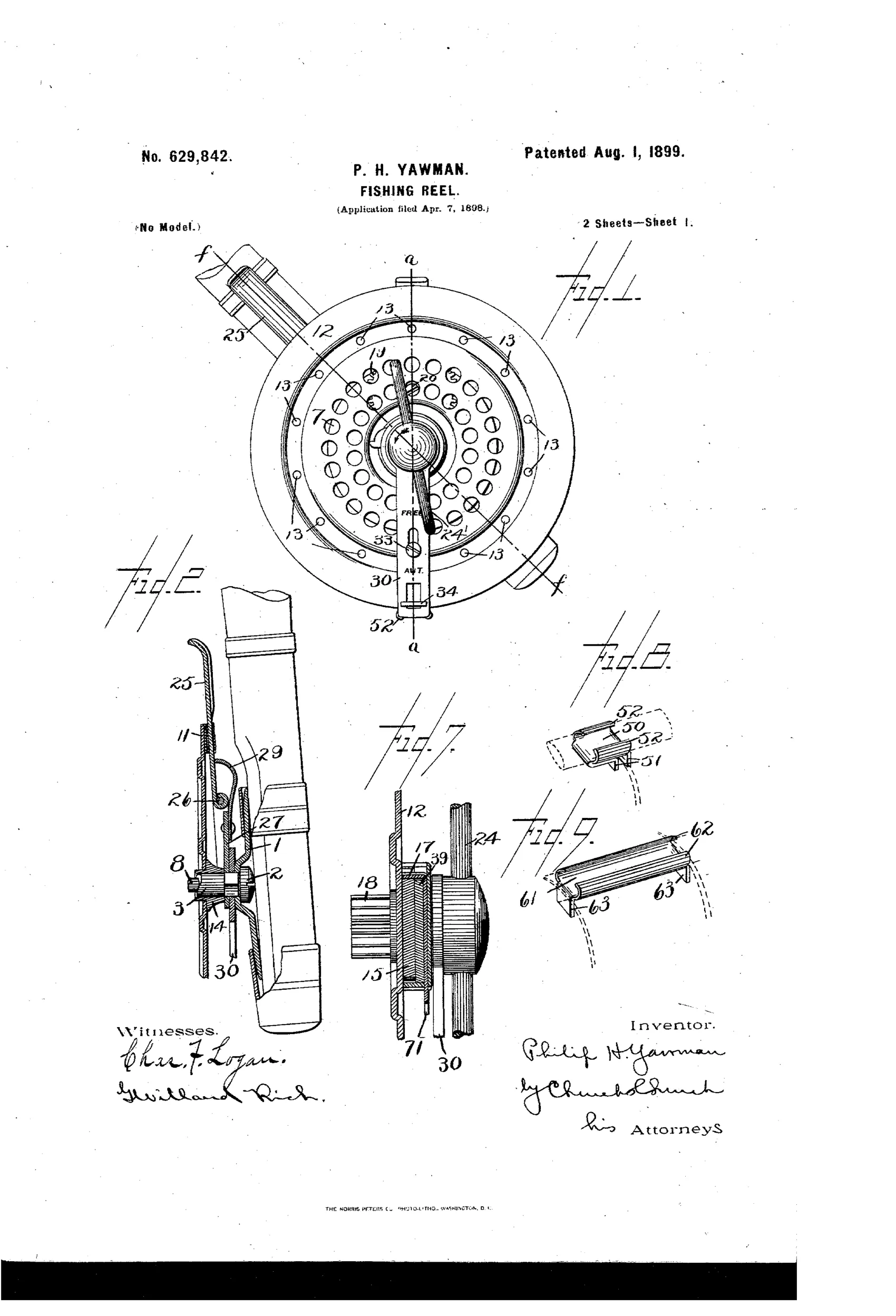
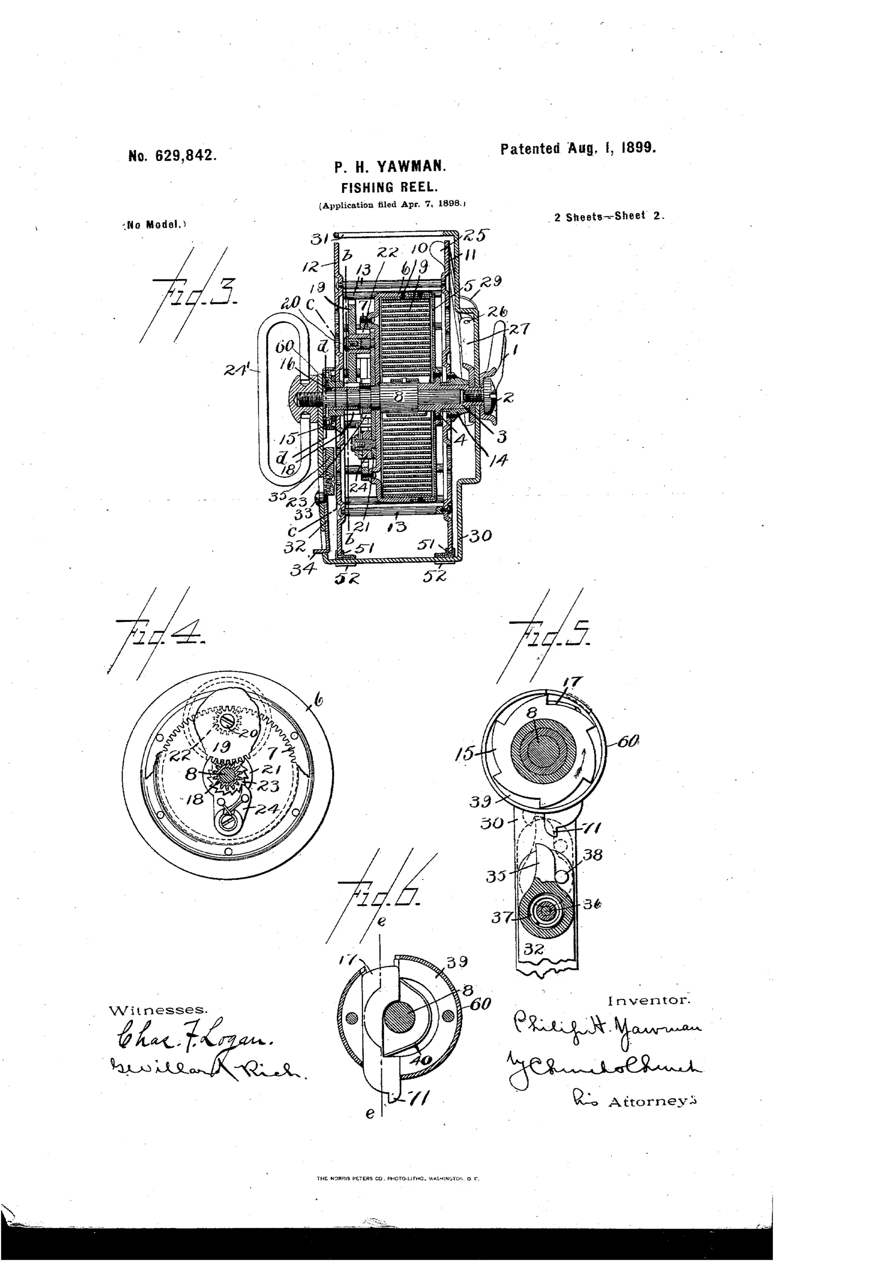
Automatic spring-driven fly-fishing reel with free-spool clutch
↻ How it works
A mainspring housed in a spring-box drives a rotary arbor through gearing that winds the line-carrying reel via a ratchet-and-pawl clutch. A manually-operated stop plate can be pushed inward to disengage this pawl from the reel's ratchet wheel, freeing the spool to rotate independently for casting. A separate friction brake, operated by the angler's finger, presses against the reel periphery to control its speed independently of the clutch mechanism, allowing the spring to be wound behind the reel without unwinding line.
↻ What was claimed
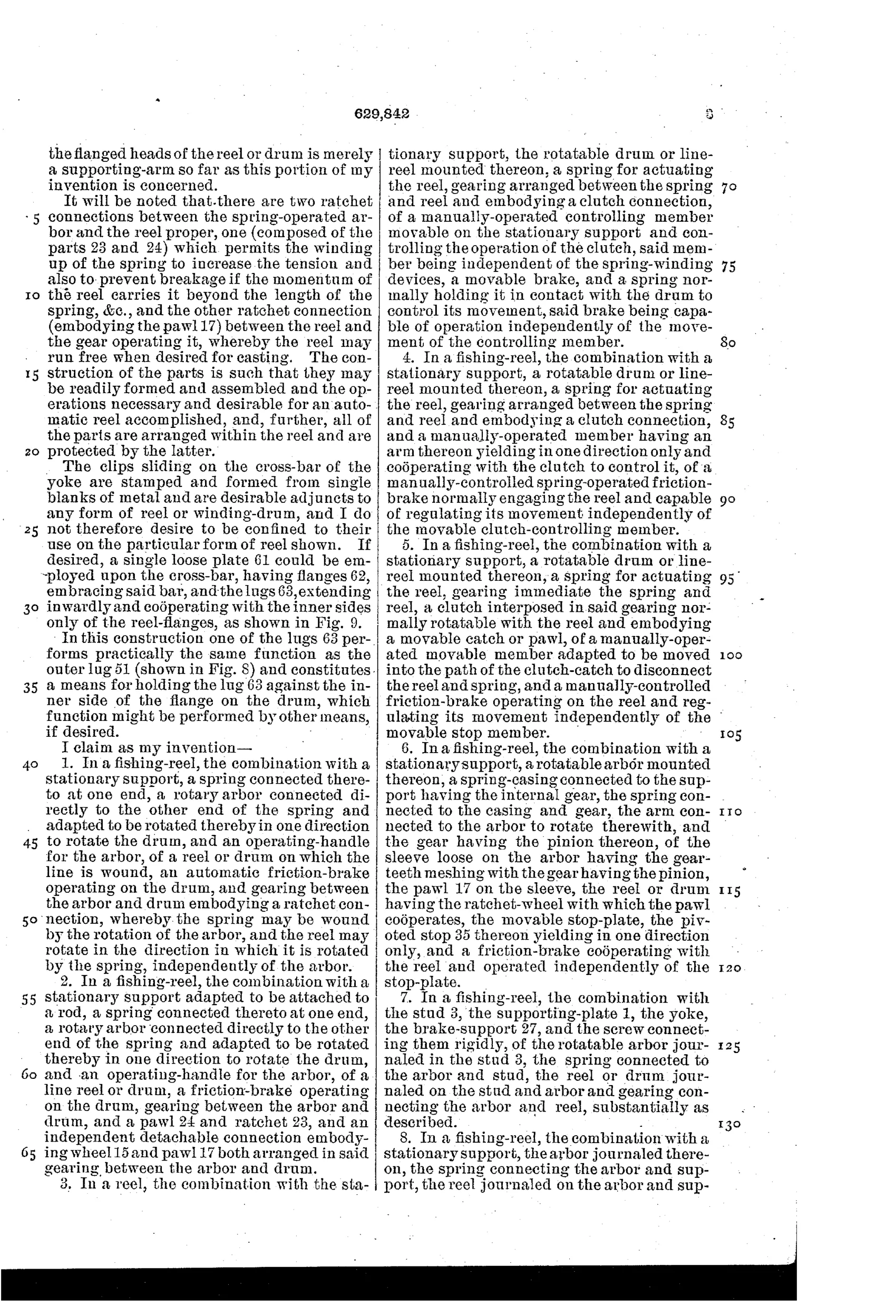
“In a fishing-reel, the combination with a stationary support, a spring connected thereto at one end, a rotary arbor connected directly to the other end of the spring and adapted to be rotated thereby in one direction to rotate the drum, and an operating-handle for the arbor, of a reel or drum on which the line is wound, an automatic friction-brake operating on the drum, and gearing between the arbor and drum embodying a ratchet connection, whereby the spring may be wound by the rotation of the arbor, and the reel may rotate in the direction in which it is rotated by the spring, independently of the arbor.”
In plain English: The reel combines a spring-driven arbor with a handle to wind it, a friction brake on the drum, and a ratchet connection so the spring can be wound up without turning the reel, while the reel still spins freely in the spring's driving direction independent of the arbor.
↻ In the inventor’s words
“the pawl 17 will be held disconnected as long as the plate 32 is moved inward and the arbor prevented from being rotated by the spring, and the object of making the stop 35 capable of yielding away from the pin 38 is to prevent damage to the parts if said stop should be moved inward while the reel is being rotated in a direction opposite to that caused by the spring, as by the pull of a fish on the line”— Philip H. Yawman, from the specification
Manufactured and sold
Yawman & Erbe manufactured automatic fly reels in quantity from the late 1890s onward, and surviving Y&E automatics carrying period patent dates are well documented among collectors.
↻ Commentary
Yawman & Erbe of Rochester were office-equipment manufacturers — filing cabinets, card indexes — and it shows here in the best way: this is precision light machinery thinking applied to a fly reel. The idea is that a mainspring, wound by the handle through a ratchet, stores energy that retrieves line automatically, while the angler's finger on a friction brake governs how fast the spool spins. The clockwork reel was not new by 1899, but Yawman's version is unusually thorough about the awkward corner cases.
Look at the stop plate arrangement in the sectional views. Pushing it inward lifts the pawl and frees the spool entirely — a genuine free-spool clutch on an automatic, so you can strip line for a cast without fighting the spring. Better still, the stop 35 is made to yield: the specification says outright that if you engage it while a fish is pulling line off, the parts give way instead of breaking. That is an inventor who has thought about what actually happens on the water, not just at the bench.
The perforated spool face in Fig. 1 nods to Orvis's 1874 ventilated design, and the separation of brake from clutch — speed control independent of engagement — is the mechanically sound heart of the thing. Yawman & Erbe automatics became the dominant name in the type for decades; this patent sits near the root of that line.
Commentary by Claude, The Fishing Reel Patent Archive’s resident enthusiast