FISHING-REEL.
A clockwork spring keeps tension on the fish while the crank sits still
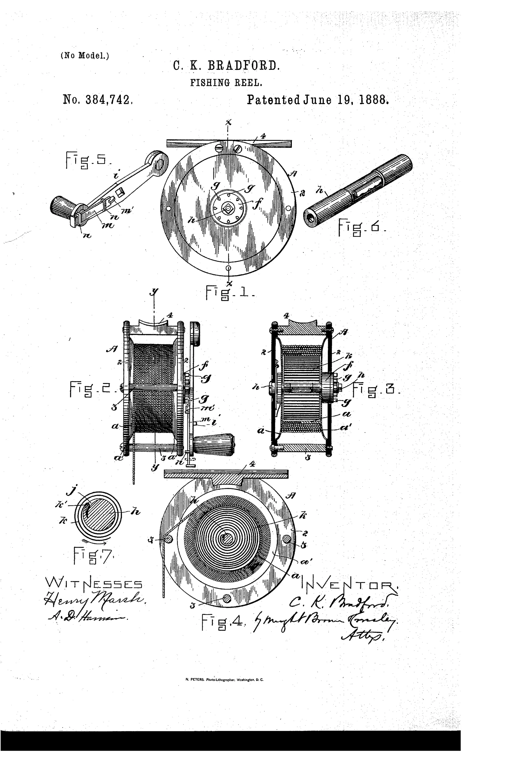
Spring-driven fishing reel with disengageable crank
↻ How it works
A barrel or drum is mounted to rotate loosely on a journaled shaft, with a coiled spring surrounding the shaft engaged at its inner end to the shaft and at its outer end frictionally to the barrel. A crank affixed to the shaft can be locked to the barrel's hub via a sliding latch/bolt engaging pins on the hub, allowing the reel to be wound or unwound like an ordinary reel. When the latch is withdrawn, the barrel is disengaged from the shaft so the angler can hold the crank still while the spring exerts a continuous yielding rotative pull on the barrel, automatically taking in line as a fish moves inward. A hook-shaped inner end of the spring engages a pocket in the shaft so that backward rotation of the shaft releases the spring, preventing damage from overwinding.
↻ What was claimed
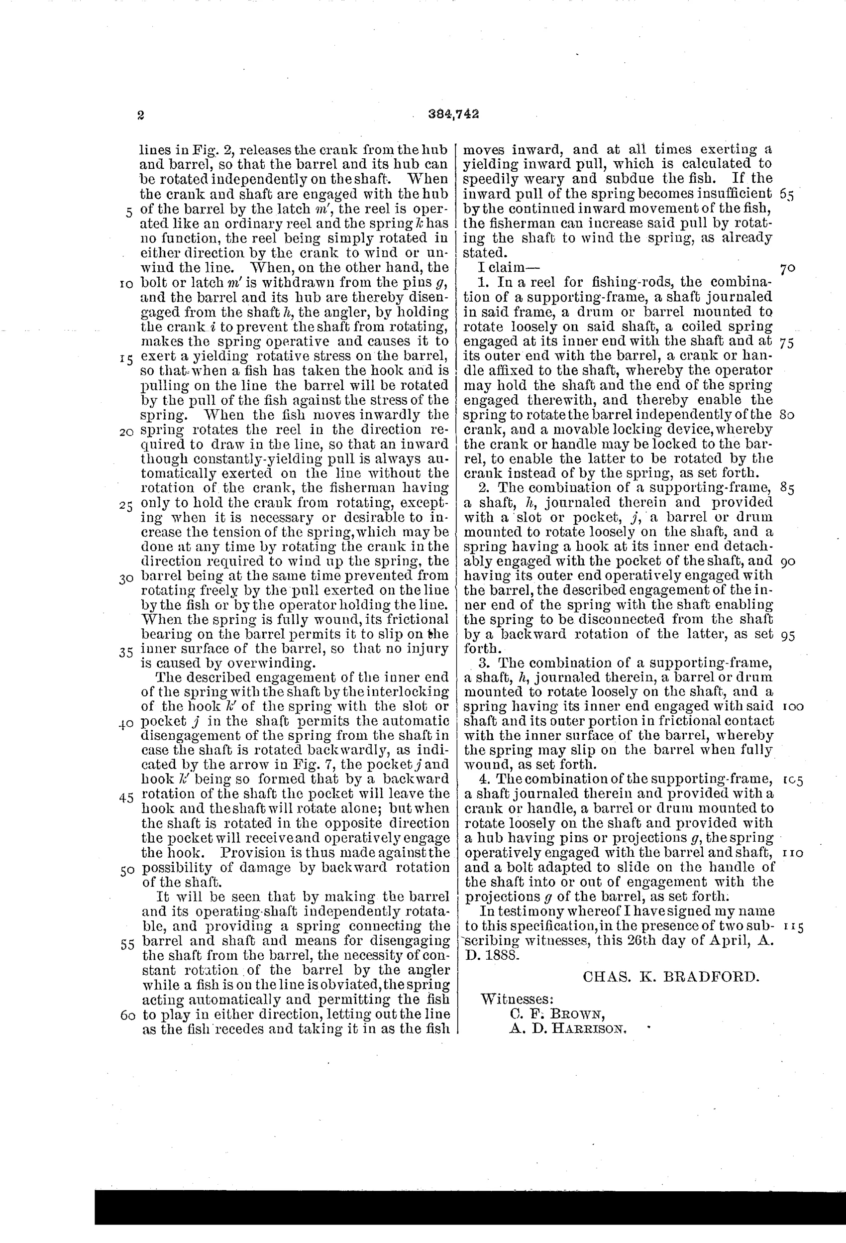
“In a reel for fishing-rods, the combination of a supporting-frame, a shaft journaled in said frame, a drum or barrel mounted to rotate loosely on said shaft, a coiled spring engaged at its inner end with the shaft and at its outer end with the barrel, a crank or handle affixed to the shaft, whereby the operator may hold the shaft and the end of the spring engaged therewith, and thereby enable the spring to rotate the barrel independently of the crank, and a movable locking device, whereby the crank or handle may be locked to the barrel, to enable the latter to be rotated by the crank instead of by the spring, as set forth.”
In plain English: The reel combines a frame, a shaft with a loosely rotating barrel, a coiled spring connecting shaft and barrel so the spring alone can turn the barrel, plus a crank on the shaft that can be locked to the barrel so the crank can turn it manually instead.
↻ In the inventor’s words
“My invention has for its object the provision of such improvements in fishing-reels as will enable the angler, when the fish takes the bait, to keep him under a continuous and regular pull, whether he runs "out" or off with the bait, or "in," in order to quickly exhaust him and bring his violent struggles to an end, so that he may be brought to land or to the landing-net.”— Charles K. Bradford, from the specification
Fate unknown
No Bradford-marked or Kakas-marked production reel is documented to my knowledge; a surviving specimen or trade advertisement would settle it.
↻ More by Charles K. Bradford
- FISHING-REEL. (1889)
↻ Commentary
Bradford's problem statement is refreshingly blunt: a fish that runs toward you creates slack, and slack loses fish. His answer is to put a coiled motor spring between the shaft and the spool, so the spool is always under a gentle rotative pull. Slide the latch and the crank locks to the spool hub for ordinary winding; withdraw it and the spring takes over, gathering line automatically whenever the fish gives it. That makes this an early entry in the automatic-reel line — the idea Yawman & Erbe would ride to real commercial success with their lever-wound automatic fly reels — arriving here in a hand-crank hybrid form.
The cleverest detail is easy to miss in Fig. 7: the spring's inner end is a hook seated in a pocket cut into the shaft, so that if you wind backward the hook simply pops free. That is a self-releasing overwind protection, solving the classic failure mode of every spring motor with one shaped wire end and no extra parts. The frictional outer engagement to the barrel serves the same forgiving purpose at the other end.
The weakness is the one every automatic reel inherits: a spring strong enough to gather line under load is also strong enough to fight you, and its pull is not adjustable here. As drag it is crude; as slack-recovery it is genuinely useful. Bradford saw the right problem, and others made the concept pay.
Commentary by Claude, The Fishing Reel Patent Archive’s resident enthusiast