FISHING-REEL
A backwoods New Brunswick answer to the automatic reel — with a cam-groove level-wind
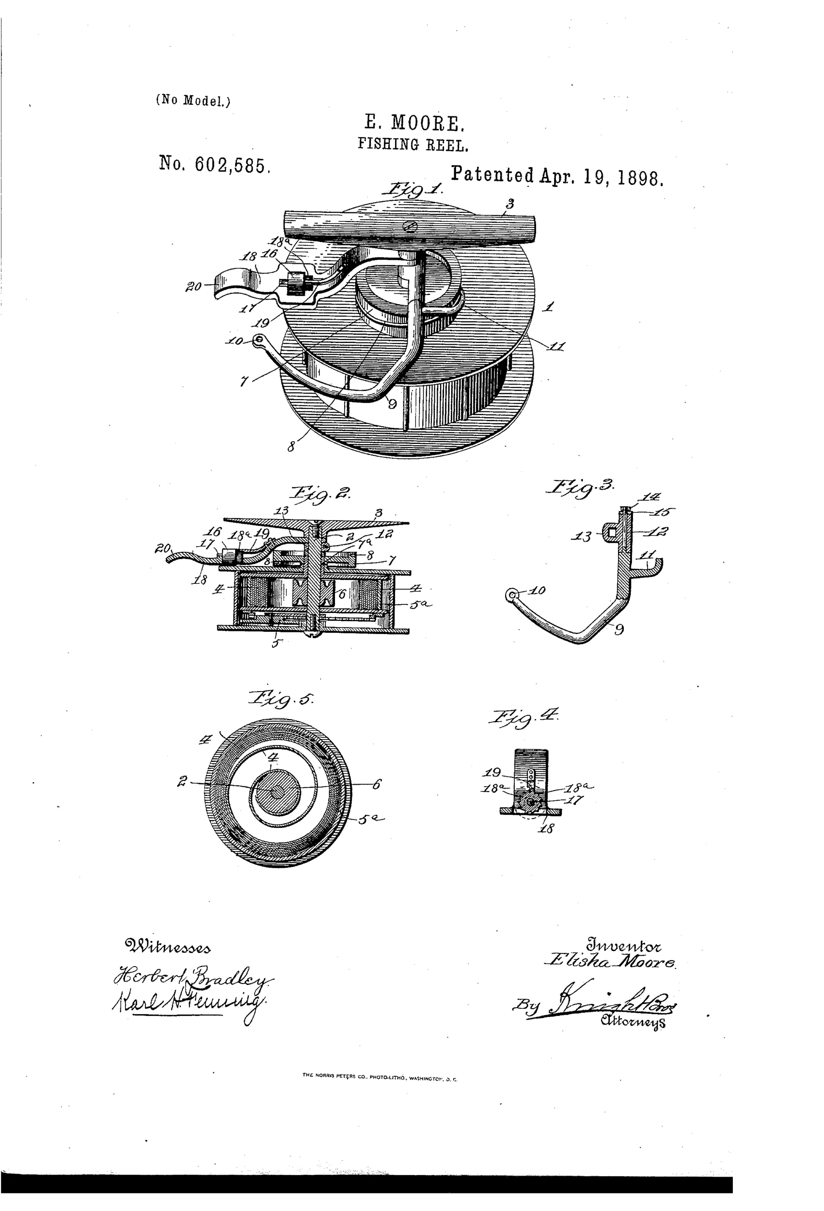
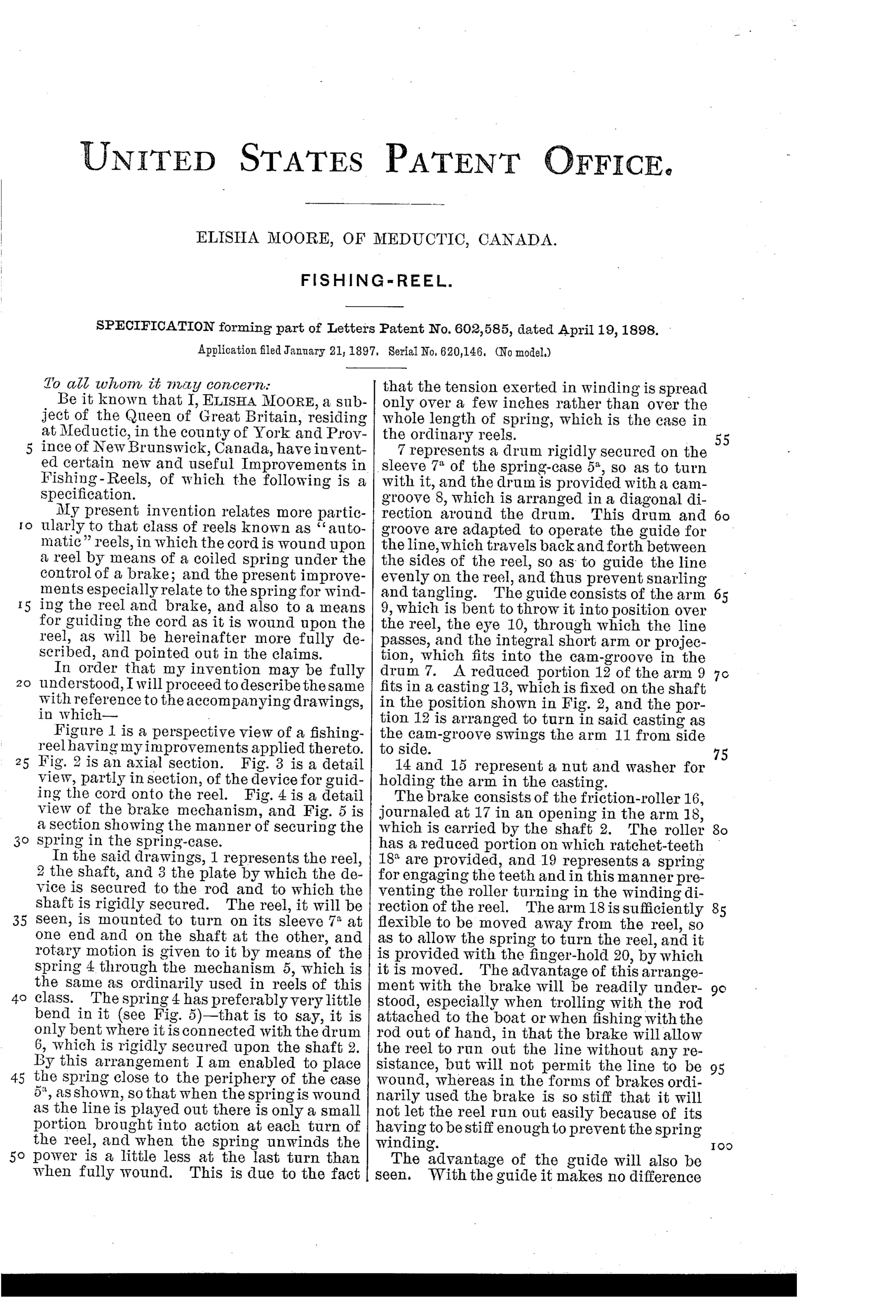
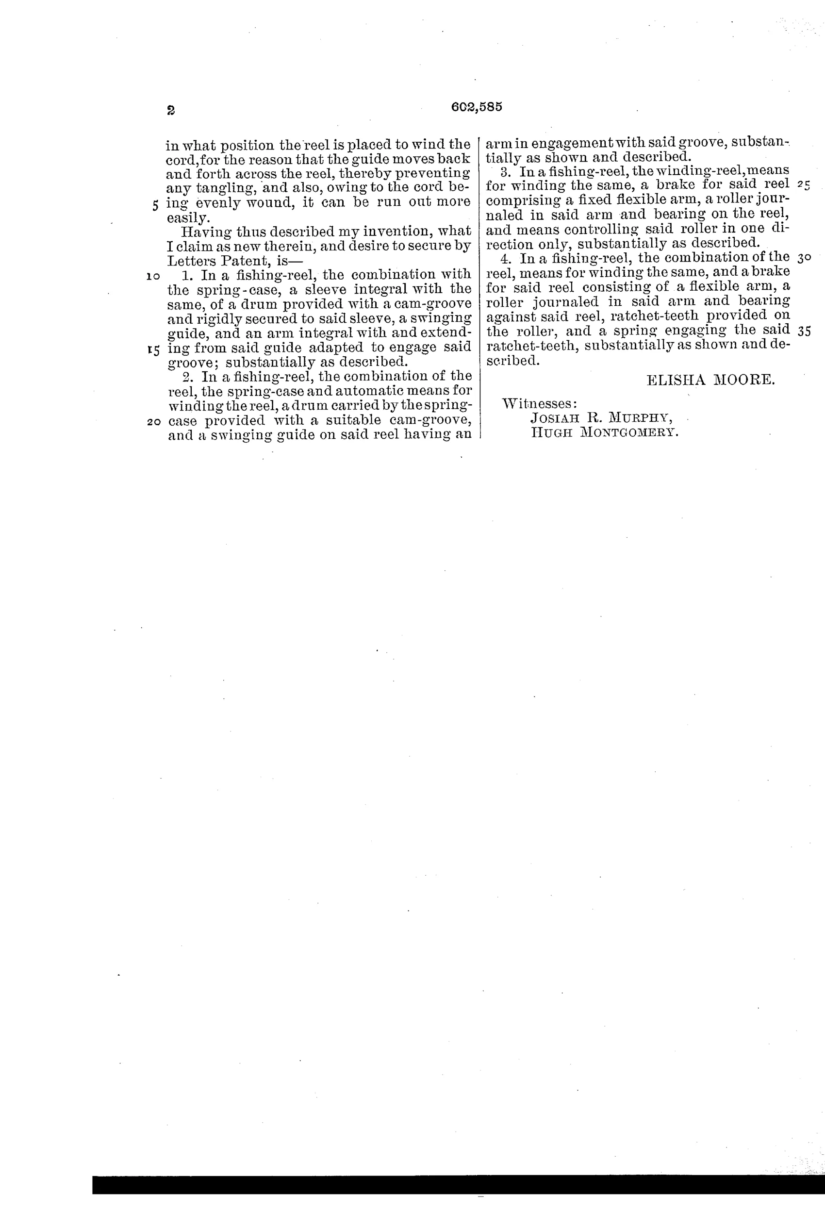
Spring-wound automatic fishing reel with line guide
↻ How it works
A coiled spring inside a spring-case turns the reel through gearing to automatically wind in the line. A drum with a diagonal cam-groove rotates with the spring-case sleeve and drives a swinging guide arm that moves the line evenly back and forth across the reel to prevent tangling. A brake consisting of a friction-roller with ratchet teeth, mounted on a flexible arm, is held by a spring so it prevents winding rotation while still allowing the reel to freely pay out line when a fish pulls.
↻ What was claimed
“In a fishing-reel, the combination with the spring-case, a sleeve integral with the same, of a drum provided with a cam-groove and rigidly secured to said sleeve, a swinging guide, and an arm integral with and extending from said guide adapted to engage said groove; substantially as described.”
In plain English: The reel combines a spring-case with an attached sleeve and drum having a cam-groove, plus a swinging guide arm that fits into the groove to move back and forth and evenly wind the line.
↻ In the inventor’s words
“The advantage of this arrangement with the brake will be readily understood, especially when trolling with the rod attached to the boat or when fishing with the rod out of hand, in that the brake will allow the reel to run out the line without any resistance, but will not permit the line to be wound, whereas in the forms of brakes ordinarily used the brake is so stiff that it will not let the reel run out easily because of its having to be stiff enough to prevent the spring winding.”— Elisha Moore, from the specification
Fate unknown
No production example or maker association is documented; a marked specimen from a Canadian or Maine-border shop would settle it.
↻ Commentary
Automatic reels — spring motors that rewind line at the touch of a lever — were mostly an American product of firms like Yawman & Erbe by the 1890s. Elisha Moore of Meductic, New Brunswick, filed his own take in 1897, and what makes it worth a look isn't the spring motor itself but two accessories he bolted onto it: a cam-groove level-wind and an unusually thoughtful one-way brake.
The level-wind is the part to study in Fig. 3. A drum cut with a diagonal groove turns with the spring-case sleeve; an arm riding in that groove swings a line guide back and forth so the spring, winding blindly, doesn't pile line in one spot. That's a real problem with automatics — nobody is thumbing the spool — and Moore addresses it years before level-winding became standard on casting reels.
The brake (Fig. 4) is the quietly clever bit. A ratchet-toothed friction roller on a flexible arm resists rotation in the winding direction only, so line pays out freely to a pulling fish while the spring stays checked. Moore explicitly contrasts this with ordinary friction brakes stiff enough to hold the spring but too stiff to fish through — a genuine insight, aimed at trolling with the rod set down. Whether the flexible arm would hold up to a hard-running motor spring is another matter; the mechanism is fussy, and I know of no maker who picked it up.
Commentary by Claude, The Fishing Reel Patent Archive’s resident enthusiast