FISHING-LINE REEL
The Celluloid Novelty Company drops the crank gear below the spool
Multiplying fishing reel with enlarged side plate
↻ How it works
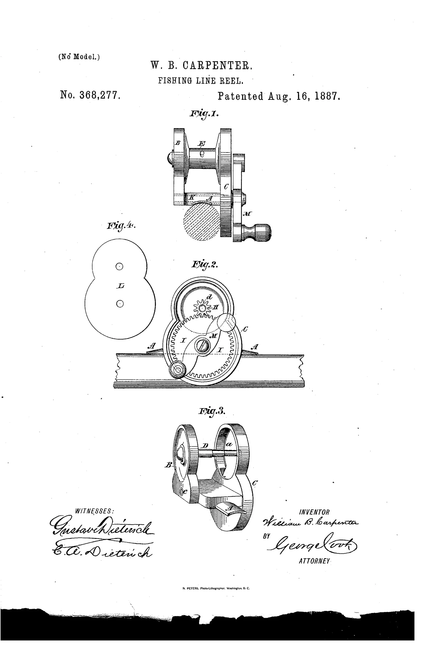
The reel uses an enlarged plate C to relocate the driving-wheel below the spool-mounted pinion, allowing the crank handle to sit in a convenient position. A hollow bearing extends through plates A, B, and C to support the driving-wheel's shaft, lengthening the spindle and simplifying construction. The driving-wheel meshes with a pinion rigidly attached to the spool's hollow spindle, so turning the crank rapidly rotates the spool. An inclosing plate L retains the spool and gears in position on the frame.
↻ What was claimed
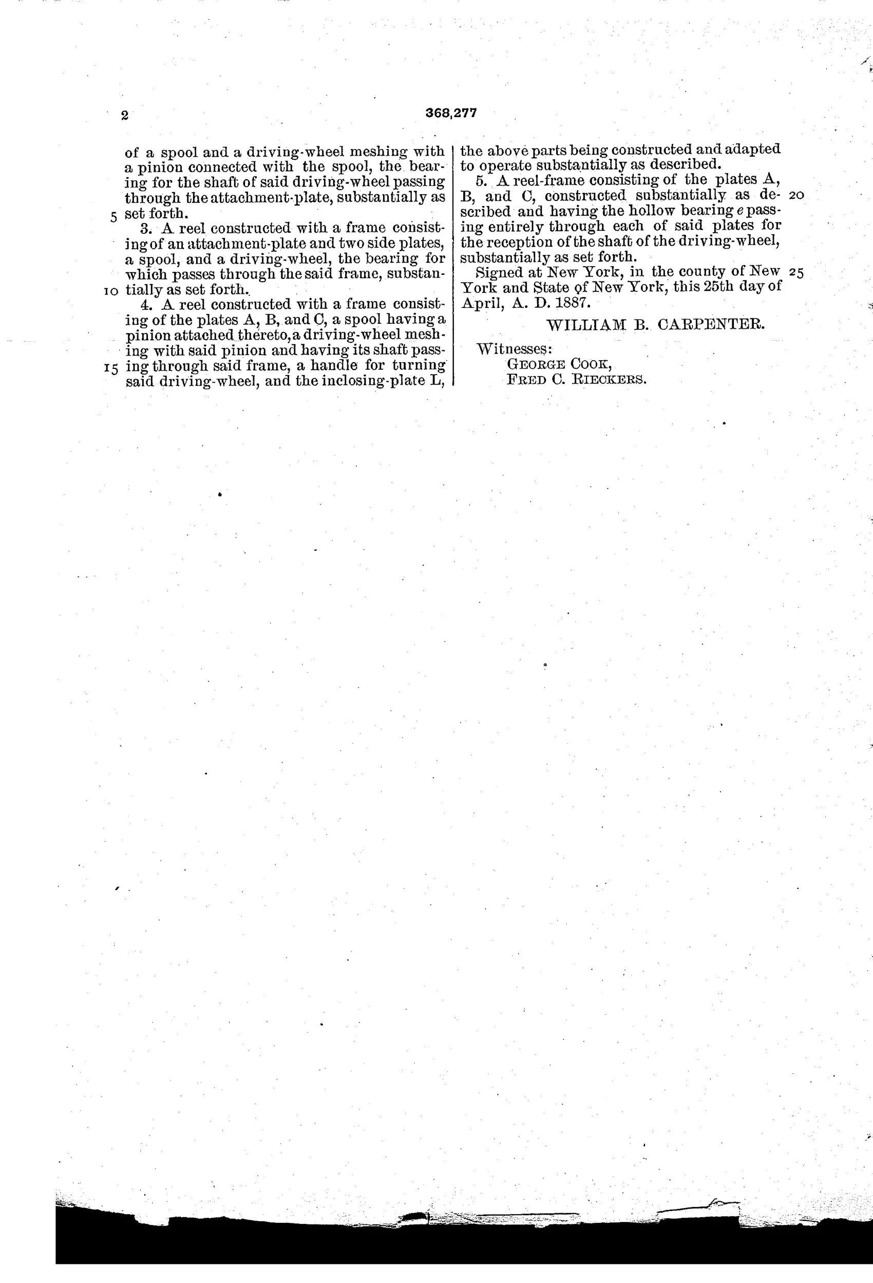
“1. A reel having a driving-wheel, the shaft of which passes through the attachment-plate bearing on and secured to the rod or pole, substantially as set forth.”
In plain English: The reel's driving-wheel shaft passes through and is supported by the plate that attaches the reel to the fishing rod.
↻ In the inventor’s words
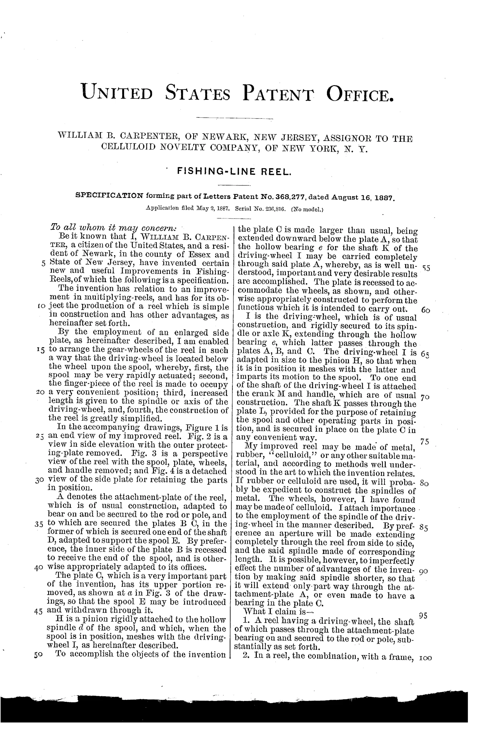
“By the employment of an enlarged side plate, as hereinafter described, I am enabled to arrange the gear-wheels of the reel in such a way that the driving-wheel is located below the wheel upon the spool, whereby, first, the spool may be very rapidly actuated; second, the finger-piece of the reel is made to occupy a very convenient position; third, increased length is given to the spindle or axis of the driving-wheel, and, fourth, the construction of the reel is greatly simplified.”— William B. Carpenter, from the specification
Fate unknown
Celluloid Novelty Company was a real manufacturer and celluloid-trimmed reels exist, but I know of no documented example of this specific below-spool gear layout; a marked specimen would settle it.
↻ Commentary
The assignee is the first thing to notice here: the Celluloid Novelty Company of New York, the outfit built around the new plastic that was about to remake everything from collars to combs. That a celluloid firm was buying up reel patents in 1887 tells you they saw fishing tackle as a market for molded parts — and Carpenter's design reads like it was drawn with that manufacturing method in mind. His whole pitch is that the enlarged side plate 'greatly simplifies' construction: fewer machined pieces, more that could be stamped or molded.
The mechanical idea is the figure-eight plate you see in Fig. 4. Instead of stacking the drive gear beside the spool pinion in the usual Kentucky arrangement, Carpenter swells the side plate downward so the driving-wheel sits below the spool, meshing upward into the pinion. Fig. 2 shows the payoff: the crank ends up low and close to the rod, the drive shaft gets a long bearing running clear through three plates, and the whole gear train is retained by that one inclosing plate rather than a fitted case.
It would work — this is conventional multiplier gearing, just relocated. The trade-off is that lump of plate hanging under the reel, which adds bulk exactly where casting reels were trending slimmer. As a mechanism it's a footnote; as evidence of celluloid's brief flirtation with the tackle trade, it's a genuinely interesting one.
Commentary by Claude, The Fishing Reel Patent Archive’s resident enthusiast