COMBINED FISHING ROD AND REEL.
Pump the handle like a shotgun and the reel winds itself
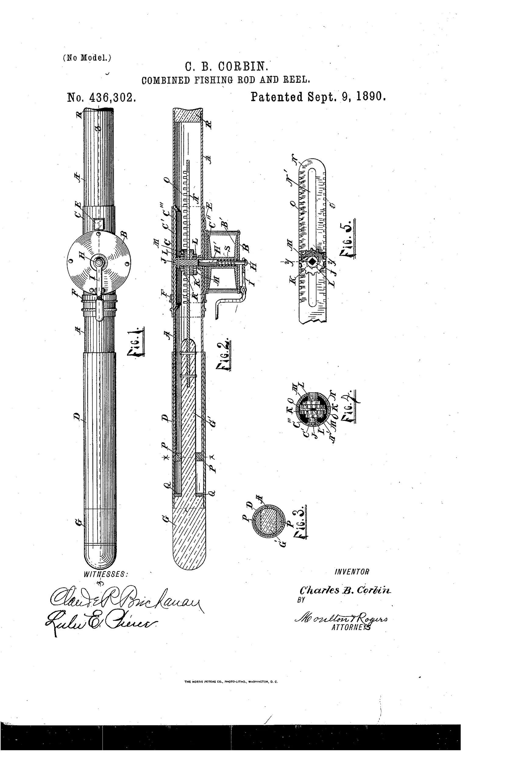
Fishing rod with reel wound by telescoping handle
↻ How it works
The lower portion of the rod consists of two tubular sections, one telescoping and reciprocating within the other. A toothed rack-bar attached to the sliding section engages loose gears and spring-pawls on a transverse shaft, which in turn drives a shaft connected to the reel spool. Reciprocating the sliding butt section back and forth thus winds the line onto the reel continuously in one direction. A pivoted trip-lever can withdraw the reel shaft from the driving mechanism, allowing the spool to spin freely and let line run out.
↻ What was claimed
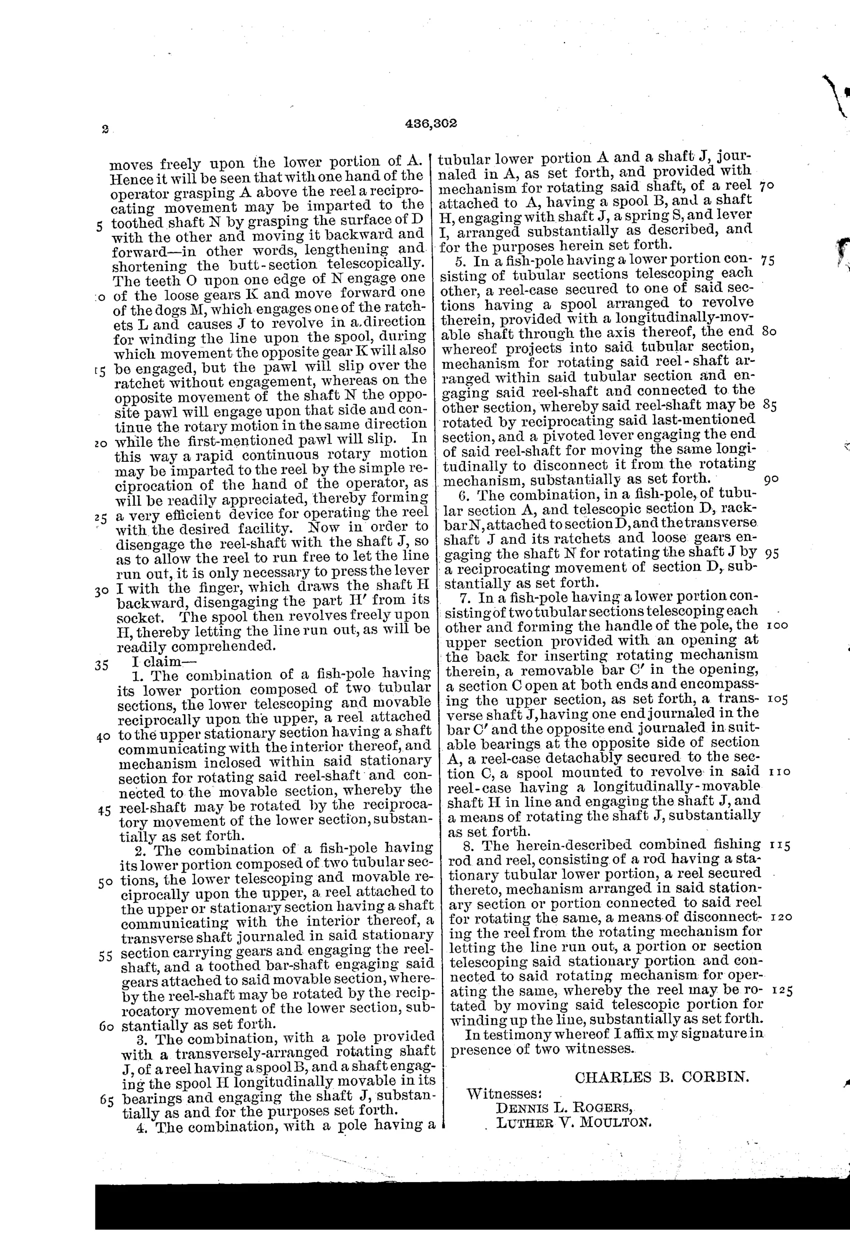
“The combination of a fish-pole having its lower portion composed of two tubular sections, the lower telescoping and movable reciprocally upon the upper, a reel attached to the upper stationary section having a shaft communicating with the interior thereof, and mechanism inclosed within said stationary section for rotating said reel-shaft and connected to the movable section, whereby the reel-shaft may be rotated by the reciprocatory movement of the lower section, substantially as set forth.”
In plain English: A fishing rod whose lower section telescopes in and out of an upper stationary section, and this back-and-forth sliding motion drives internal gearing that turns the reel to wind in the line.
↻ In the inventor’s words
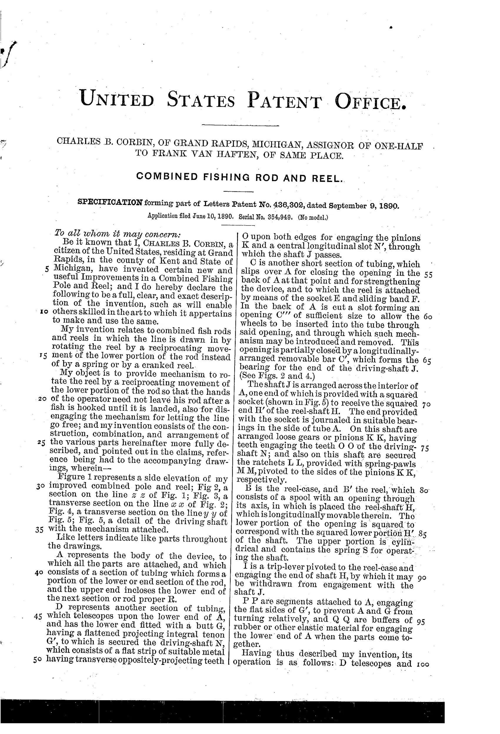
“My object is to provide mechanism to rotate the reel by a reciprocating movement of the lower portion of the rod so that the hands of the operator need not leave his rod after a fish is hooked until it is landed, also for disengaging the mechanism for letting the line go free.”— Charles B. Corbin, from the specification
Fate unknown
No production example or maker connection is documented; a surviving marked rod would settle it, though the complexity argues against manufacture.
↻ More by Charles B. Corbin
- FISH-LINE REEL. (1894)
↻ Commentary
Corbin's idea is essentially a slide-action fishing rod. The butt section telescopes over the upper section, and inside runs a toothed rack-bar. Slide the butt in and out and the rack drives a pair of loose gears fitted with spring-pawls on a cross shaft — a ratchet arrangement that turns wasted return strokes into continuous one-direction rotation of the reel spool. It's the same trick a Yankee push-drill screwdriver uses, applied to landing a fish. The stated goal is honest and appealing: never take your hands off the rod from strike to net.
The drawing rewards a close look. Fig. 2's section shows how much machinery is hiding inside what looks, in Fig. 1, like an ordinary rod with a side-mounted reel: rack, gears, pawls, and a trip-lever that pulls the reel shaft clear of the works so the spool can run free for a cast or a strong fish. That free-spool disconnect is the most practical touch in the whole patent — without it the device would be a line-breaker.
The trouble is mechanical, not conceptual. Every pump stroke shortens your effective rod, jerks the tip, and telegraphs motion straight down the line to the fish. Add water, sand, and grit working into an open telescoping joint full of pawls, and you have a maintenance headache Kentucky-style crank reels simply didn't have. It sits in the long, mostly fruitless nineteenth-century line of combined rod-and-reel schemes: inventive, sincere, and outflanked by the plain crank handle.
Commentary by Claude, The Fishing Reel Patent Archive’s resident enthusiast