IMPROVEMENT IN FISHING-LINE REELS.
A reel buried inside the rod itself, with a crank that folds away
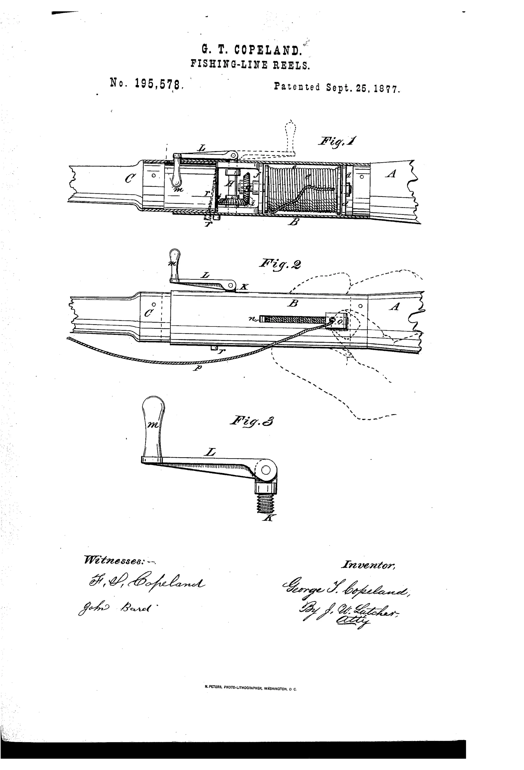
Detachable-crank fishing reel with line guide
↻ How it works
The reel-case B unites the rod butt A with the remaining rod portion C and houses a spool e on shaft g meshed by bevel-gears i i to a crank-shaft H within a slidable bearing-frame f. A detachable screw-shaft K carries a pivoted crank L that can be inserted or reversed through an opening in the case to avoid snagging obstructions while angling. A line-guide o slides in a longitudinal slot n over the spool to distribute the line, manipulated by the angler's thumb, while a transverse spring-brake r engages the gear i through a notched slot to check the spool's motion and moderate the line's run.
↻ What was claimed
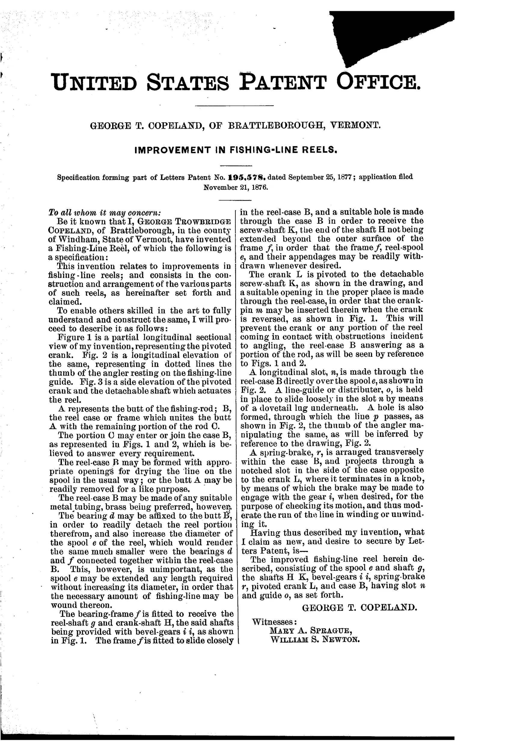
“The improved fishing-line reel herein described, consisting of the spool e and shaft g, the shafts H K, bevel-gears i i, spring-brake r, pivoted crank L, and case B, having slot n and guide o, as set forth.”
In plain English: The claim covers the complete reel assembly: the spool and its shaft, the crank and screw shafts, the bevel gears, a spring-operated brake, a fold-away pivoted crank, and a slotted case with a sliding line guide, all working together as described.
↻ In the inventor’s words
“This will prevent the crank or any portion of the reel coming in contact with obstructions incident to angling, the reel-case B answering as a portion of the rod, as will be seen by reference to Figs. 1 and 2.”— George Trowbridge Copeland, from the specification
Fate unknown
No manufactured example or maker connection is documented for Copeland's in-rod design; a surviving marked specimen would settle it.
↻ Commentary
Copeland's answer to the eternal snagging problem was radical: get rid of the reel as a protruding object entirely. His case B is a section of the rod, splicing the butt to the tip, with the spool turned sideways inside and driven through bevel gears from a crank that screws in through the wall. Fig. 3 shows the trick a casual glance misses — the crank L pivots on the shaft K, so it can be reversed or laid flat, and the whole thing unscrews when you want a clean cylinder to carry through brush. His own words say it plainly: nothing on the reel touches 'obstructions incident to angling.'
Two details are ahead of their time. The sliding guide o in the slot n is a thumb-operated line distributor — a manual level-wind, twenty-odd years before geared level-winds became the trade's obsession. And the spring-brake r bearing on the gear is a crude drag, moderating the run of the line rather than just clicking.
The trouble is everything else. Bevel gears sap cranking power, the enclosed spool holds little line and dries poorly, and building the reel into the rod means the rod and reel live and die together. In-rod reels resurface every generation and never stick, and this 1877 Vermont entry is an early lesson in why: clever housing, compromised fishing tool. Still, as a bundle of ideas — folding crank, line guide, spring drag — it's a remarkably busy little patent.
Commentary by Claude, The Fishing Reel Patent Archive’s resident enthusiast