FISH-LINE REEL.
A reel hidden inside the rod butt, cranked by a squeezing finger lever
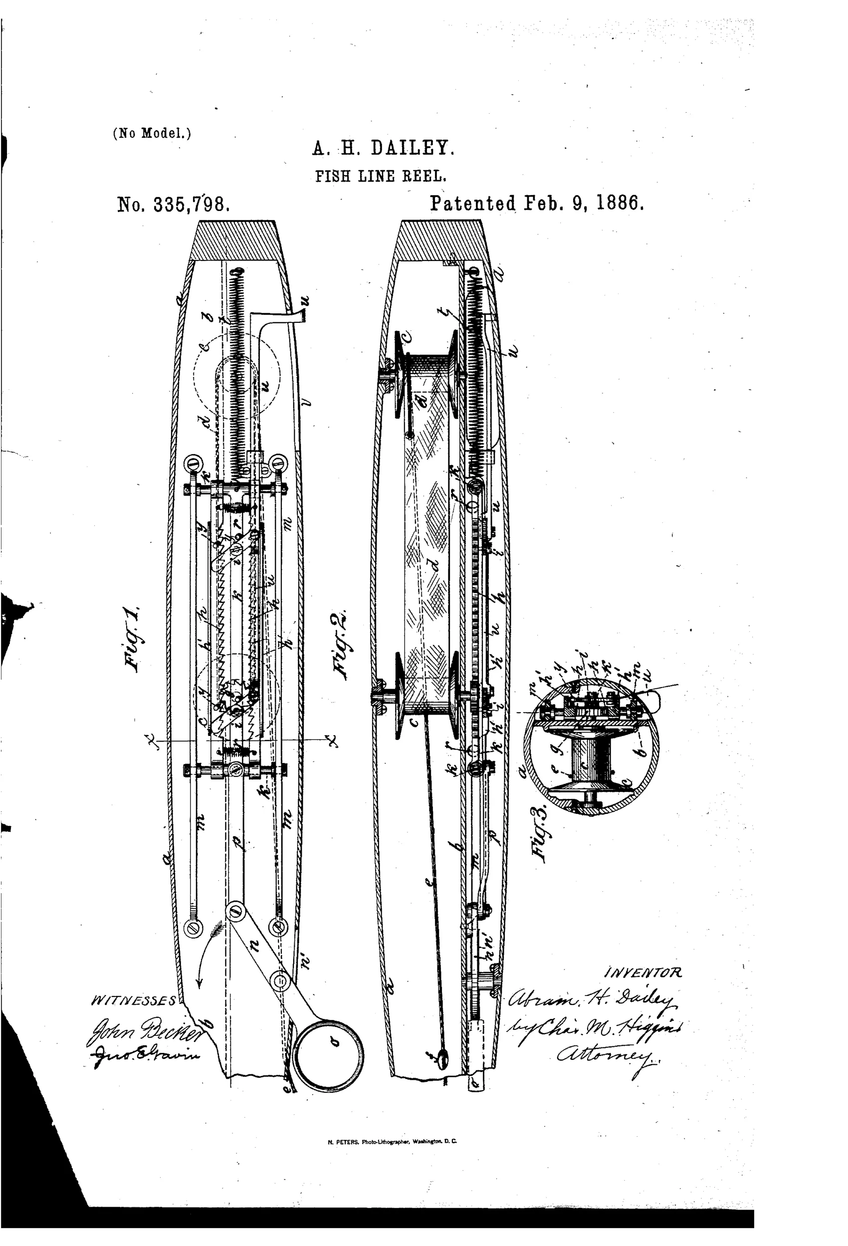
Ratchet-driven fish-line reel concealed inside pole butt
↻ How it works
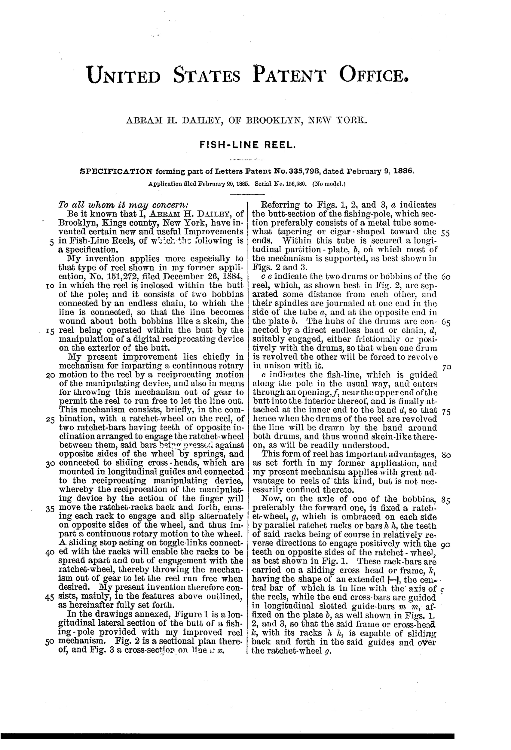
A ratchet wheel fixed on the axle of one of two internal bobbins is flanked on opposite sides by two spring-pressed rack bars carried on a sliding frame. A finger lever pivoted near the top of the butt, linked to the sliding frame, is worked back and forth by the angler's finger against a return spring, causing the rack bars to alternately engage and slip on the ratchet teeth so as to impart continuous rotary motion to the reel from a simple reciprocating motion. The two bobbins are joined by an endless band or chain so that turning one turns the other, winding the line skein-like about both drums as it enters through an opening near the top of the butt. To let the line run out freely, a sliding stop on the exterior of the butt pushes toggle-links that spread the rack bars apart, disengaging them from the ratchet wheel.
↻ What was claimed
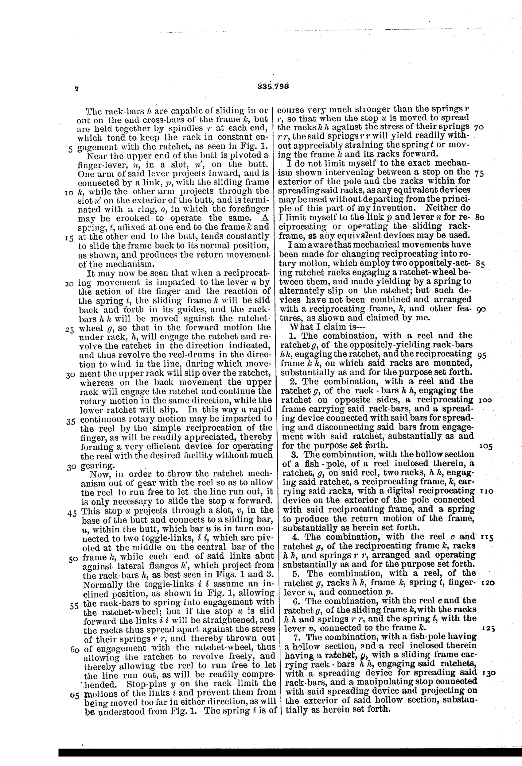
“1. The combination, with a reel and the ratchet g, of the oppositely-yielding rack-bars h h, engaging the ratchet, and the reciprocating frame k k, on which said racks are mounted, substantially as and for the purpose set forth.”
In plain English: The reel combines a ratchet wheel with two spring-loaded rack bars mounted on a sliding frame that engage opposite sides of the ratchet to turn it.
↻ In the inventor’s words
“the reel being operated within the butt by the manipulation of a digital reciprocating device on the exterior of the butt.”— Abram H. Dailey, from the specification
Paper patent — likely never produced
The internal complexity, unconventional skein winding, and absence of any documented specimen make production very unlikely, though a marked example would overturn this.
↻ Patented the same day
- FISHING ROD AND REEL. — Abram H. Dailey
- REEL FOR FISHING-RODS. — Elisha J. Martin
↻ More by Abram H. Dailey
- FISHING ROD AND REEL. (1886)
↻ Commentary
Dailey's 1886 patent throws out the crank handle entirely. Instead of a spool mounted on a reel seat, two bobbins live inside the hollow butt of the rod, joined by an endless band so they turn together, winding the line skein-fashion around both. The angler drives it with a finger lever near the grip: each squeeze slides a frame carrying two spring-pressed rack bars that engage opposite sides of a ratchet wheel, so both the pull and the spring return advance the reel. It converts a trigger-squeeze into continuous rotation — the same trick as a ratchet screwdriver, applied to fishing.
The drawing rewards a close look. Fig. 1 shows how much machinery is packed into that tapering butt: guide rods, the sliding frame, the return spring, and the toggle-links that spread the rack bars apart when a sliding stop on the exterior is pushed — that's the free-spool release, and it's a genuinely tidy detail. Fig. 2 shows why two bobbins were needed at all: a single drum wide enough to hold useful line wouldn't fit in the butt's diameter, so the line is wound like yarn on a skein-winder between the pair.
As a piece of the category's story, this is a dead end, and an honest one. While vom Hofe, a fellow Brooklynite, was refining the conventional multiplier a few miles away, Dailey was asking whether the reel needed to be visible at all. Retrieval by finger-pumping would be slow and tiring, and a skein wound around two drums invites tangles the moment tension slackens. Clever kinematics in service of a question few anglers were asking.
Commentary by Claude, The Fishing Reel Patent Archive’s resident enthusiast