FISHING-REEL ATTACHMENT.
A spring-loaded mechanical thumb from Pensacola, with an off switch for light casts
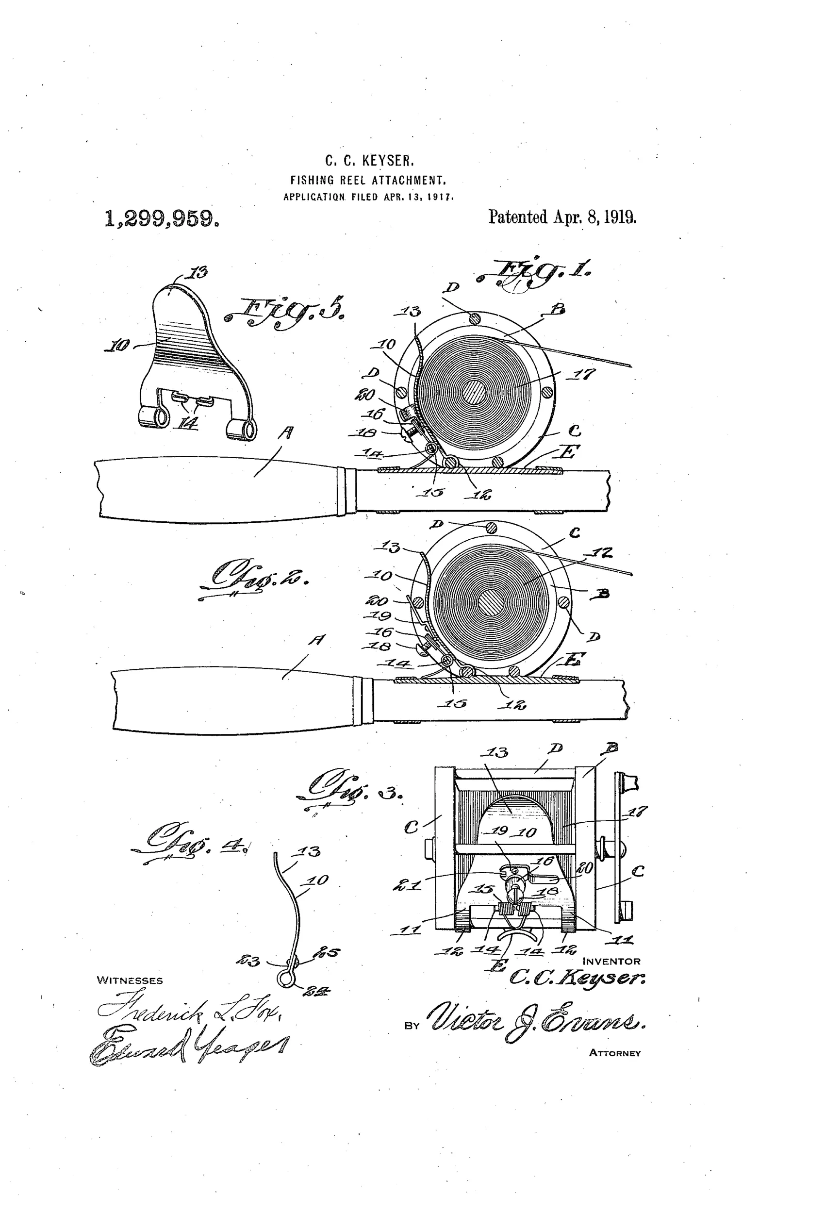

Anti-backlash thumber attachment for a fishing reel
↻ How it works
A pivoted plate mounted on a transverse rod of the reel is yieldably pressed by a coiled spring against the coils of line wound on the spool. The spring tension is regulated by an adjusting screw threaded through a nut carried on the spring's terminals, allowing the user to set the pressure of the plate against the line. During a cast the pressure lets the reel pay out line freely, but as the casting's momentum is spent the plate checks the reel's movement, preventing backlashing and tangling. A pivoted latch element with an offset extremity can be swung behind an adjacent rod to hold the plate entirely out of contact with the reel and line when the attachment is not wanted, as in very light bait casting.
↻ What was claimed
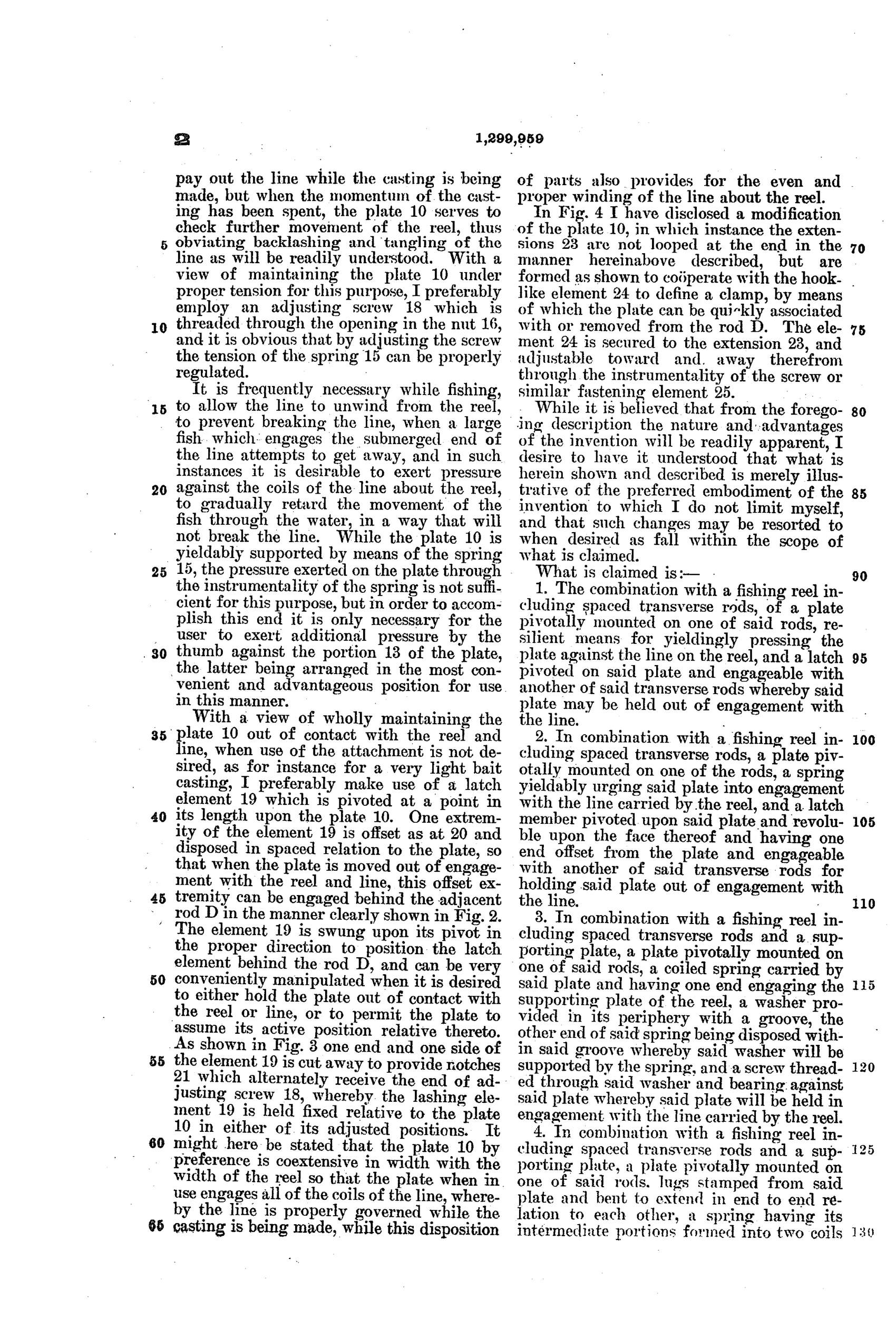
“The combination with a fishing reel including spaced transverse rods, of a plate pivotally mounted on one of said rods, resilient means for yieldingly pressing the plate against the line on the reel, and a latch pivoted on said plate and engageable with another of said transverse rods whereby said plate may be held out of engagement with the line.”
In plain English: A spring-loaded plate pivots on one reel rod to press against the line, and a separate latch on the plate can hook onto another rod to hold the plate away from the line when not needed.
↻ In the inventor’s words
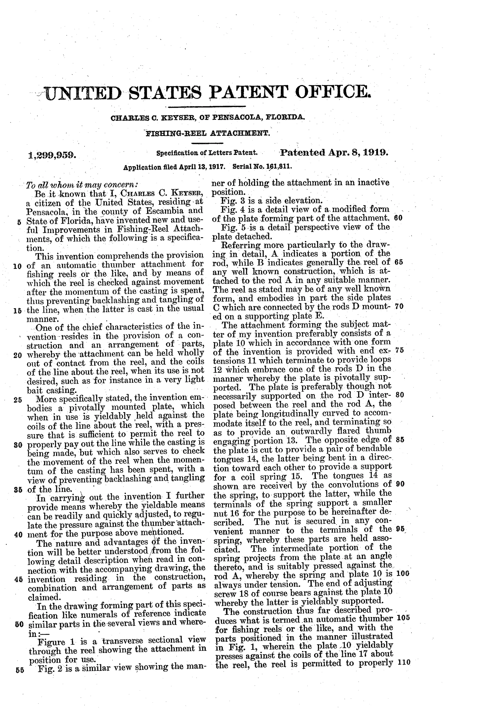
“This invention comprehends the provision of an automatic thumber attachment for fishing reels or the like, and by means of which the reel is checked against movement after the momentum of the casting is spent, thus preventing backlashing and tangling of the line, when the latter is cast in the usual manner.”— Charles C. Keyser, from the specification
Fate unknown
No production example or maker association is documented for this attachment; a marked specimen or trade-catalog listing would settle it.
↻ Commentary
By 1917 the anti-backlash problem had become the great obsession of the casting-reel world, and most inventors attacked the spool itself — governors, brakes, centrifugal weights. Keyser's approach is humbler and more literal: he mechanized the thumb. A curved plate pivots on one of the reel's cross rods and a coil spring presses it directly against the coils of line on the spool, doing exactly what an educated thumb does — riding the line lightly during the cast and choking off the spool as the lure's momentum dies.
Two details in the drawing reward a close look. First, the adjusting screw threaded through a nut on the spring's ends (item 21 in Fig. 3) gives the angler a real tension setting rather than a fixed pressure, which matters because the right drag varies with lure weight. Second, and more thoughtful, the little pivoted latch shown in Fig. 2 hooks behind an adjacent rod to swing the plate completely clear — Keyser knew that on very light casts any added friction kills distance, and he designed for it instead of pretending otherwise.
The weakness is inherent to line-riding thumbers: the plate bears on wet, sandy line, wearing braided silk and gathering grit. South Bend and others eventually made line-riding anti-backlash devices commercially, but those descend from their own patents, not this one. Keyser's is a sensible, workmanlike entry in a very crowded race.
Commentary by Claude, The Fishing Reel Patent Archive’s resident enthusiast