FISHING-REEL.
An 1883 free-spool clutch, built into the rod itself, decades early
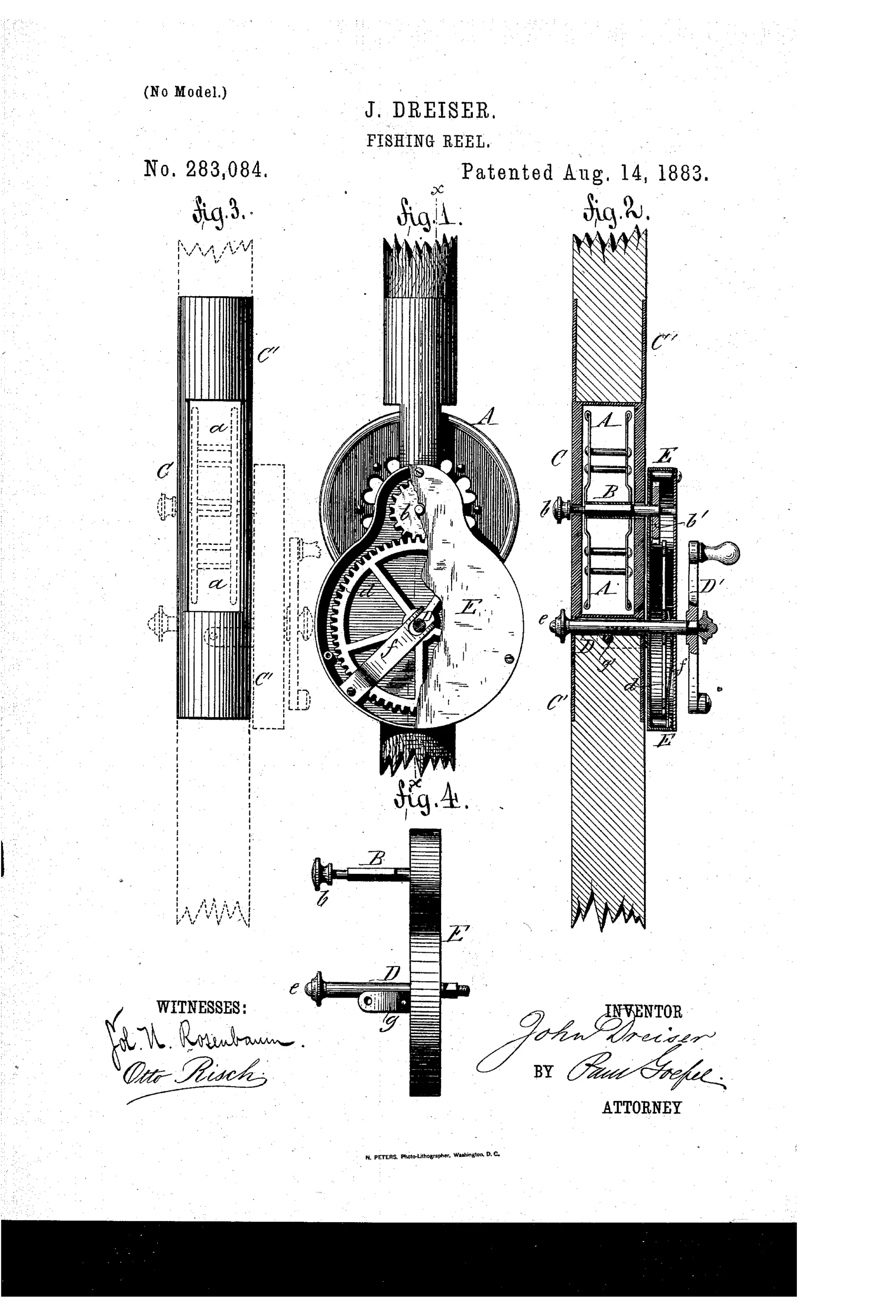
Fishing reel with disengageable multiplying gear crank
↻ How it works
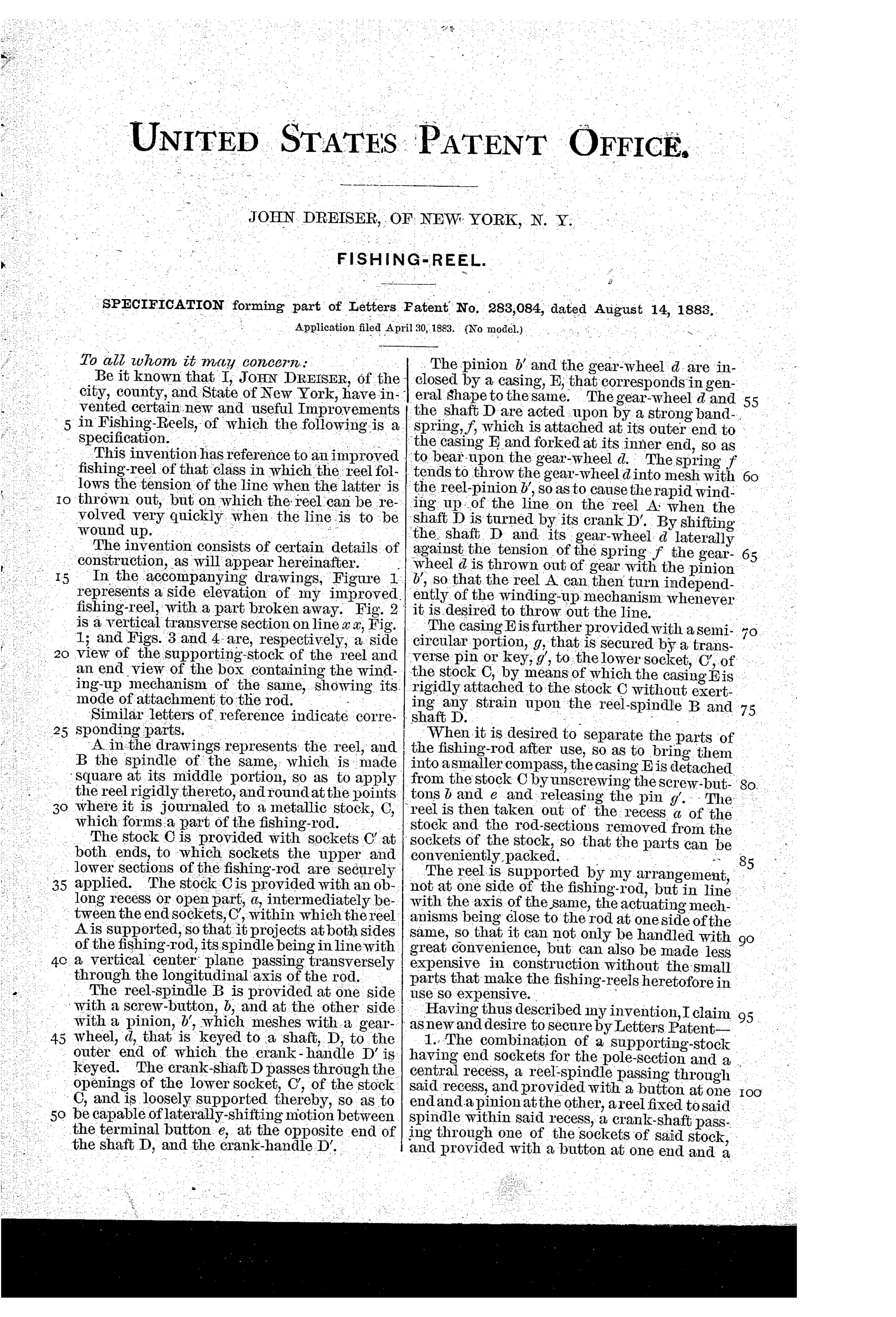
The reel A is fixed to a square-sectioned spindle B that is journaled in a metallic stock C located in line with the rod's axis rather than beside it. A pinion b' on the spindle meshes with a gear-wheel d keyed to a crank-shaft D, which is spring-loaded (spring f) to press the gear into mesh so turning the crank-handle D' rapidly winds the line. The crank-shaft D can be shifted laterally against the spring's tension to disengage the gear-wheel from the pinion, letting the reel spin freely so line pays out under its own tension when cast. A casing E encloses the pinion and gear-wheel and is detachably pinned to the stock C, and the whole assembly (reel, casing, and rod sections) can be unscrewed and separated for compact packing.
↻ What was claimed
“The combination of a metallic stock, C, having sockets C' for the rod-sections, a reel, A, supported in a recess of the stock, a reel-spindle, B, having pinion b', a crank-shaft, D, supported loosely in one of the sockets, a gear-wheel, d, keyed to the crank-shaft D, and a spring, f, pressing upon said gear-wheel d, so as to throw it into or out of mesh with the pinion b' by the laterally-shifting motion of the crank-shaft D, substantially as and for the purpose set forth.”
In plain English: A reel assembly where a spring-pressed gear can be shifted sideways along its crank-shaft to engage or disengage from the reel's pinion, allowing the angler to switch between free-spinning cast and geared rapid winding.
↻ In the inventor’s words
“The reel is supported by my arrangement, not at one side of the fishing-rod, but in line with the axis of the same, the actuating mechanisms being close to the rod at one side of the same, so that it can not only be handled with great convenience, but can also be made less expensive in construction without the small parts that make the fishing-reels heretofore in use so expensive.”— John Dreiser, from the specification
Fate unknown
No marked example or maker connection is documented for Dreiser's integrated design; a surviving rod-and-stock assembly would settle it.
↻ Commentary
Two ideas collide here, and both are ahead of their time. First, Dreiser mounts his reel in line with the rod's axis — the reel sits in a recess of a metal stock C that doubles as a rod section, with sockets threading the rod pieces to either end. The whole thing unscrews for compact packing. Second, and more interesting to the mechanism-minded: the crank-shaft D can slide laterally against spring f, throwing gear-wheel d out of mesh with pinion b'. Push the crank in for geared multiplying retrieve; let it out and the spool spins free for the cast.
That is, functionally, a free-spool clutch — the thing that would become standard on casting reels well into the twentieth century. Fig. 2 shows it plainly: the crank-shaft riding loose in its socket, the spring pressing the gear home. It's crude compared to later throw-out mechanisms, but the logic is exactly right: disconnect the gear train's inertia from the spool when line pays out.
Where it stumbles is the in-line layout. A reel buried in the rod handle offers no easy thumbing of the spool, awkward line access, and a stock that must be as strong as the rod it interrupts. Dreiser boasts of dispensing with the expensive small parts of conventional reels, but he trades them for a fussy integrated assembly. The clutch idea deserved a better home, and eventually got one — elsewhere.
Commentary by Claude, The Fishing Reel Patent Archive’s resident enthusiast