FISHING-REEL.
A Brooklyn free-spool clutch in 1883, decades before the idea caught on
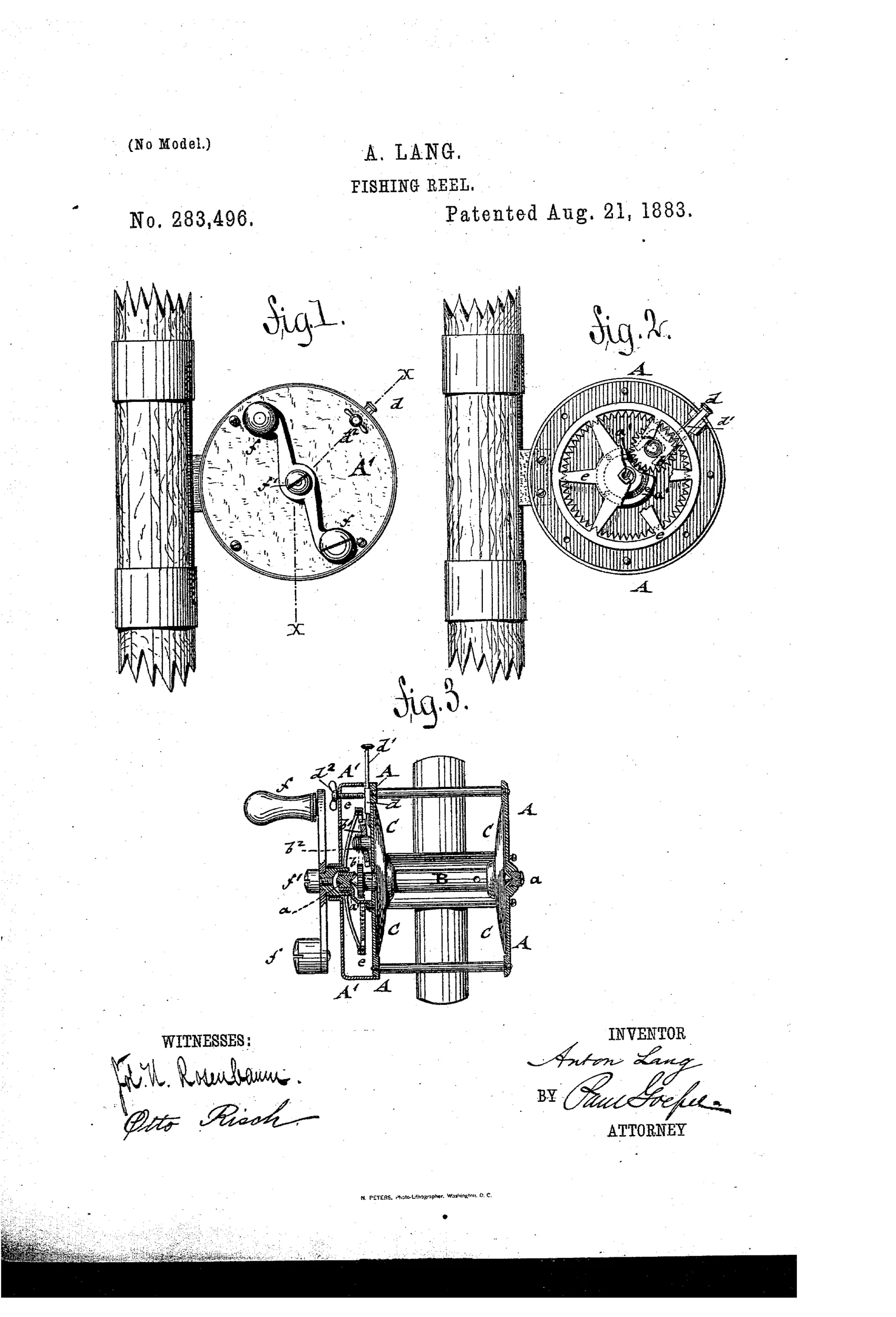
A multiplying fishing reel with disengageable gearing
↻ How it works
The spindle carries end disks that form the line-winding pulley and turns in steel bearings set in the frame. A fixed spindle-pinion meshes, through a spring-pressed intermediate pinion, with a larger internal gear-wheel connected to the crank handle. A forked slide-piece, locked by a thumb-screw, pushes the intermediate pinion into mesh for rapid multiplying wind-up or pulls it out so the spindle spins freely during casting or when a fish pulls line out.
↻ What was claimed
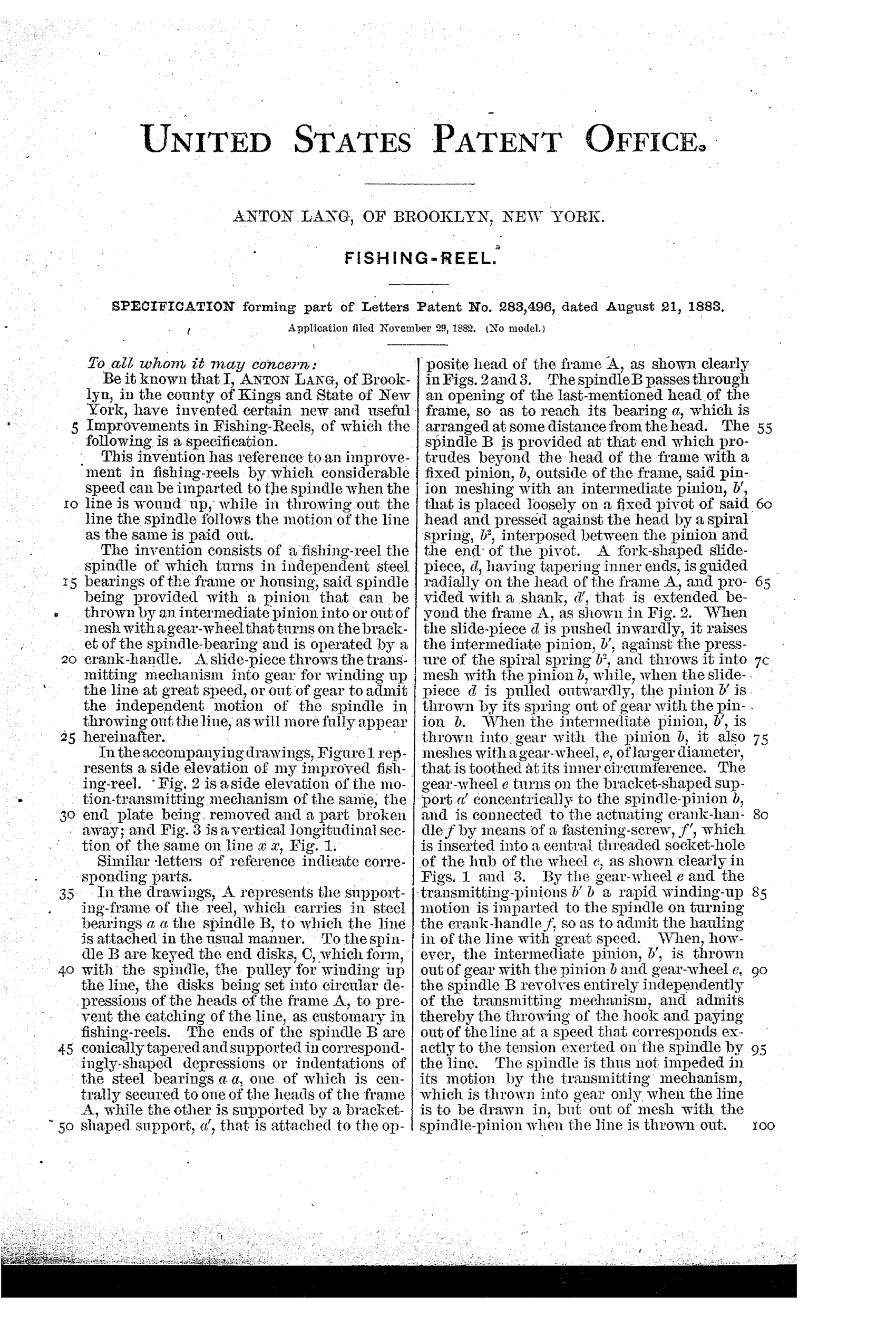
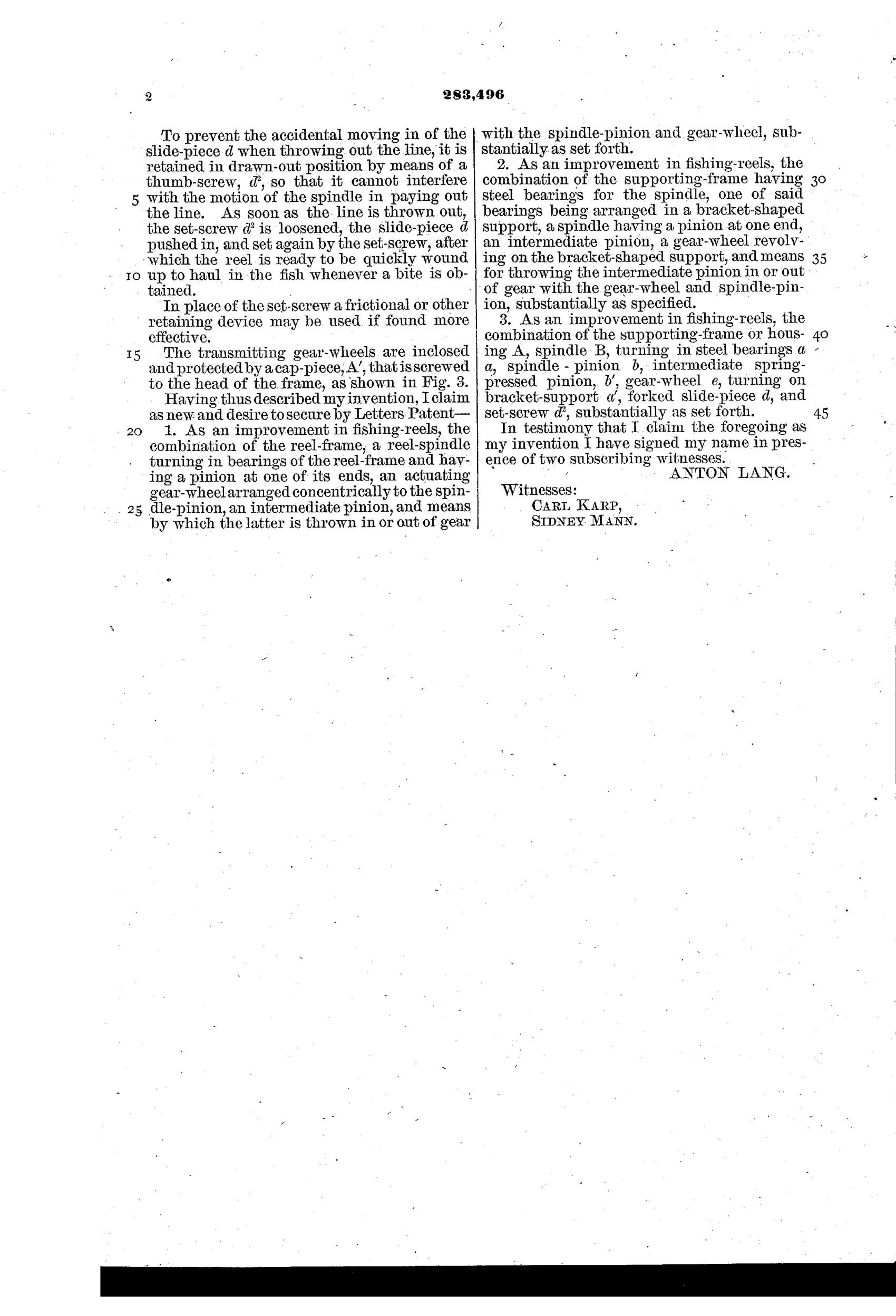
“As an improvement in fishing-reels, the combination of the reel-frame, a reel-spindle turning in bearings of the reel-frame and having a pinion at one of its ends, an actuating gear-wheel arranged concentrically to the spindle-pinion, an intermediate pinion, and means by which the latter is thrown in or out of gear with the spindle-pinion and gear-wheel, substantially as set forth.”
In plain English: The reel combines a frame, a spindle with an end pinion, a concentric crank-driven gear-wheel, and an intermediate pinion that can be engaged or disengaged to connect or free the spindle from the crank mechanism.
↻ In the inventor’s words
“The spindle is thus not impeded in its motion by the transmitting mechanism, which is thrown into gear only when the line is to be drawn in, but out of mesh with the spindle-pinion when the line is thrown out.”— Anton Lang, from the specification
Fate unknown
No production example marked with Lang's name or this patent date is documented; a surviving specimen would settle it.
↻ Commentary
The problem Lang attacks is the multiplying reel's built-in contradiction: the gearing that speeds retrieve also drags on the spool during the cast, because every turn of the spool has to spin the whole gear train and crank backwards. His answer is what we would now call a free-spool clutch. An intermediate pinion sits between the spindle pinion and a large internal gear on the crank, carried on a spring-pressed forked slide locked by a thumb-screw. Slide it in, and you have a fast multiplier; slide it out, and the spool spins on its steel bearings with nothing attached but its own end disks.
Fig. 3 rewards a close look. Note the internal (ring) gear driven by the crank rather than a simple spur pair — that keeps the crank concentric and leaves room for the throw-out pinion to swing clear. The clamp-style rod mounting in Figs. 1 and 2, gripping the rod between two sections, is old-fashioned even for 1883 and hints at a British single-action heritage grafted onto American multiplying ideas.
The thumb-screw is the weak spot: fumbling a lock screw at the moment a fish strikes is not what an angler wants. Later free-spool designs used quick levers or push-buttons for exactly that reason. Still, as an early statement of the free-spool principle, this is a genuinely forward-looking patent, not a curiosity.
Commentary by Claude, The Fishing Reel Patent Archive’s resident enthusiast