FISHING-REEL
A clockwork mainspring hidden in the rod handle plays the fish for you
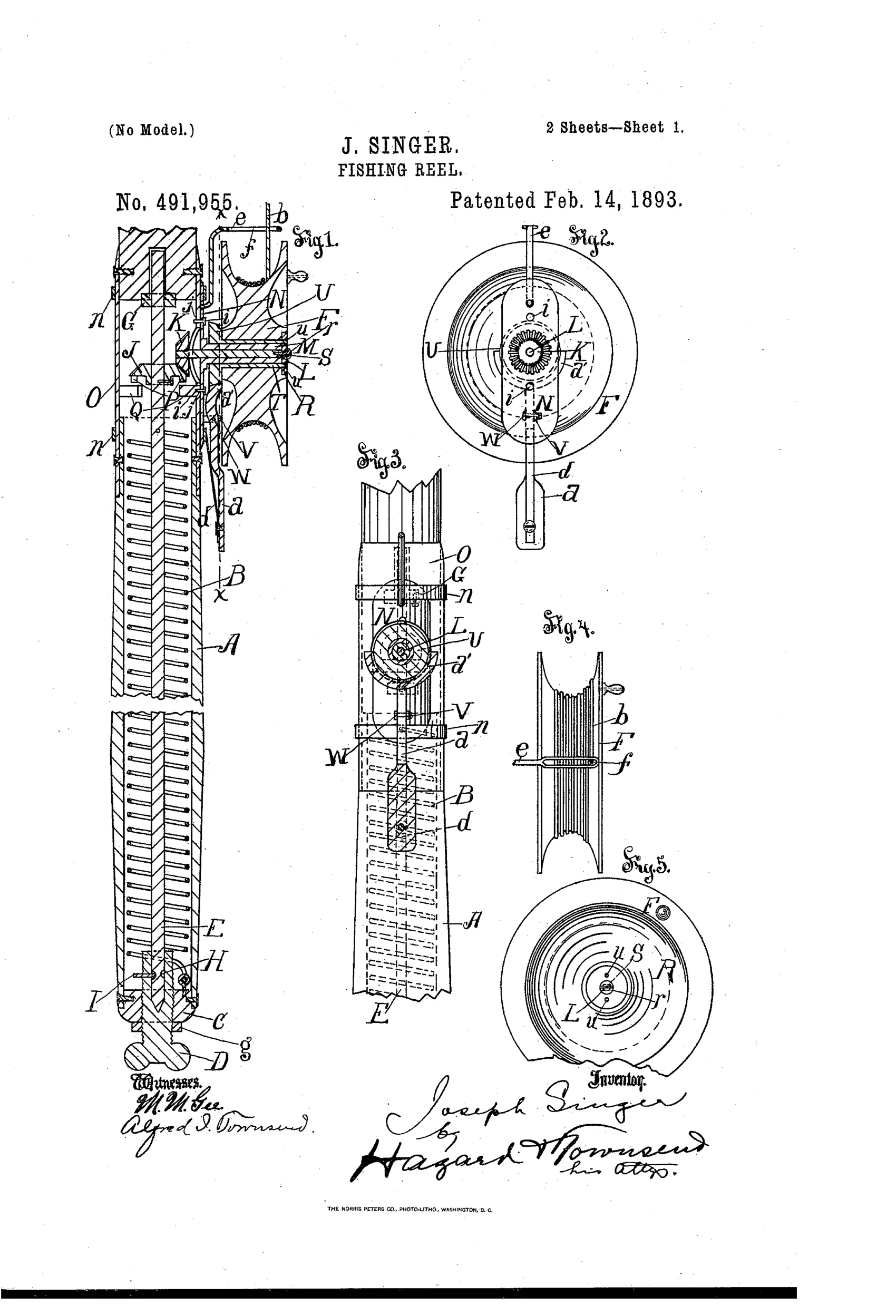
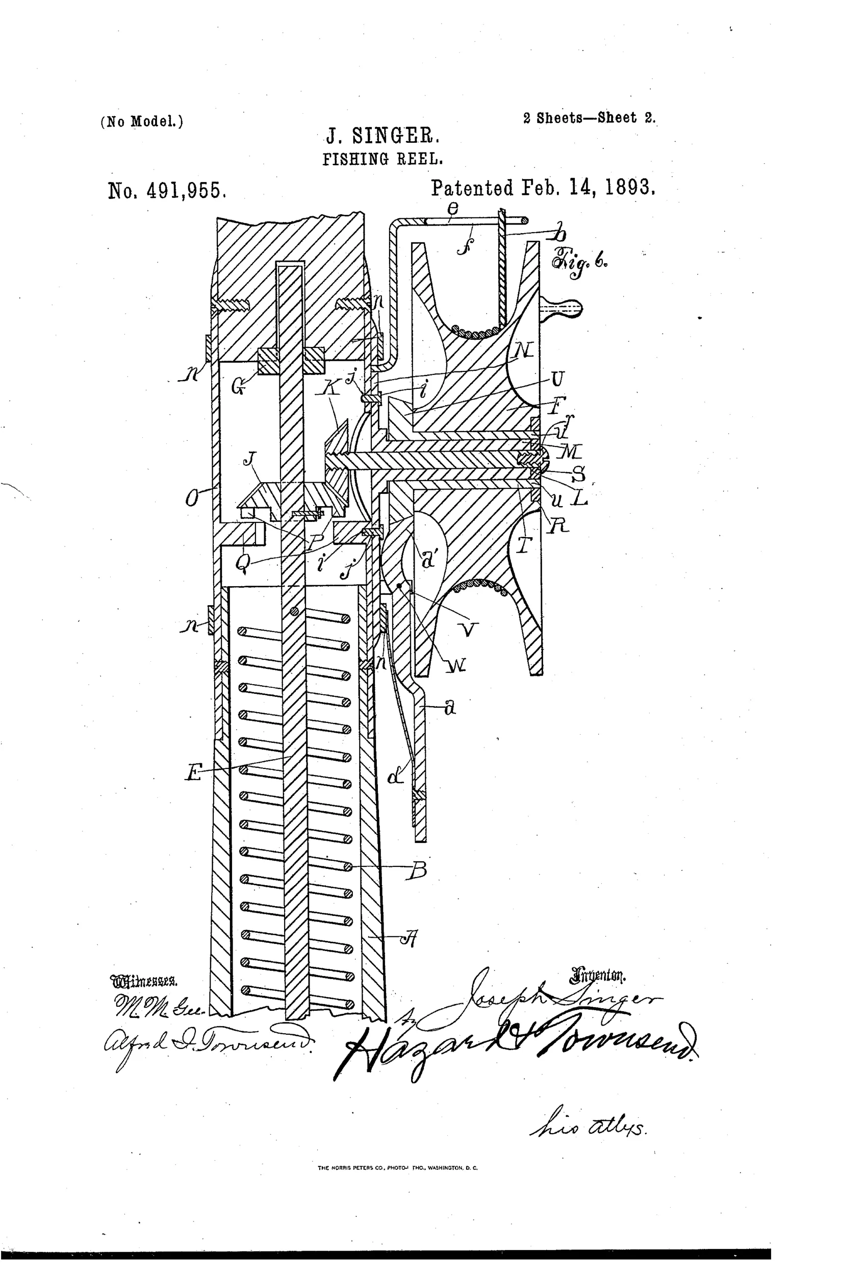
Spring-actuated fishing reel with disengageable drive
↻ How it works
A coiled spring housed in the rod's hollow handle drives an axially movable shaft carrying a driving cog wheel J that meshes with a driven cog K on a spindle L connected to the reel F. Moving journal post D shifts the shaft E axially, disengaging wheel J from K so the reel can be used by hand without unwinding the spring, and downward-projecting lugs P engage fixed lugs Q on the rod to stop the driving wheel from spinning when disengaged. A beveled friction brake wheel U on the reel's spindle is engaged by a pivoted brake shoe a', held by spring d, which can be released by moving the lever toward the rod rather than sideways. The reel attaches via a removable plate N with a hollow journal sleeve M, so that when detached no shaft projects from the rod, and pins i on the plate engage holes j in a ferrule O to prevent shifting.
↻ What was claimed
“The combination set forth of a fishing rod having a hollow handle; a spring actuated driving wheel situated in such handle; a reel attaching plate arranged for attachment to the rod and provided with an outwardly projecting hollow journal sleeve; a reel journaled upon such journal sleeve; a reel actuating spindle journaled in such hollow journal sleeve and attached at its outer end to the reel and provided upon its inner end with a driven wheel arranged to engage the spring actuated driving wheel within the rod when the reel is attached to the rod, and a suitable stop arranged to engage the spring actuated driving wheel within the rod when the reel is disengaged therefrom.”
In plain English: The invention combines a hollow-handled rod with an internal spring-driven wheel, a removable reel-mounting plate with a hollow sleeve, and a reel whose spindle carries a driven wheel that engages the spring drive when attached, with a stop to hold the driving wheel still when the reel is removed.
↻ In the inventor’s words
“In practice the operator unreels sufficient line and makes a cast; the brake a prevents the reel from being revolved by the spring. When a fish is hooked, the sportsman loosens the brake and the spring B acting upon the reel allows the line to unreel and when the fish turns, the slack is instantly taken up, thus automatically playing the fish without any effort on the part of the sportsman.”— Joseph Singer, from the specification
Fate unknown
No production example of this rod-and-reel combination is documented in the collecting literature; a marked specimen would settle it.
↻ Commentary
Joseph Singer's idea is essentially an automatic fly reel a decade before Yawman & Erbe made the type famous — but with the whole clockwork moved out of the reel and into the hollow butt of the rod itself. Fig. 1 shows the coiled spring B running the length of the handle, driving cog J, which meshes with the driven wheel K on the reel spindle. His sales pitch is right there in the specification: hook a fish, release the friction brake, and the spring pays out line under tension and snatches up slack whenever the fish turns, 'automatically playing the fish without any effort on the part of the sportsman.'
The mechanically thoughtful part is the disengagement. Sliding the shaft axially uncouples the spring drive so the reel works as an ordinary hand-crank without unwinding the mainspring, and lugs P and Q lock the driving wheel so stored energy doesn't bleed away. The removable mounting plate N leaves no shaft poking out of the rod when the reel comes off — a detail showing Singer thought about how the thing would actually be carried and cased.
The fatal flaw is the marriage of rod and reel: you can't use this reel on any other rod, or any other reel on this rod, and a hollow handle stuffed with a mainspring makes for a heavy, fragile butt. Later automatics wisely put the spring in the reel housing. Singer had the right instinct pointed at the wrong component.
Commentary by Claude, The Fishing Reel Patent Archive’s resident enthusiast