IMPROVEMENT IN FISHING-LINE REELS
An adjustable, thumb-operated drag brake in 1864 — decades before the anti-backlash craze
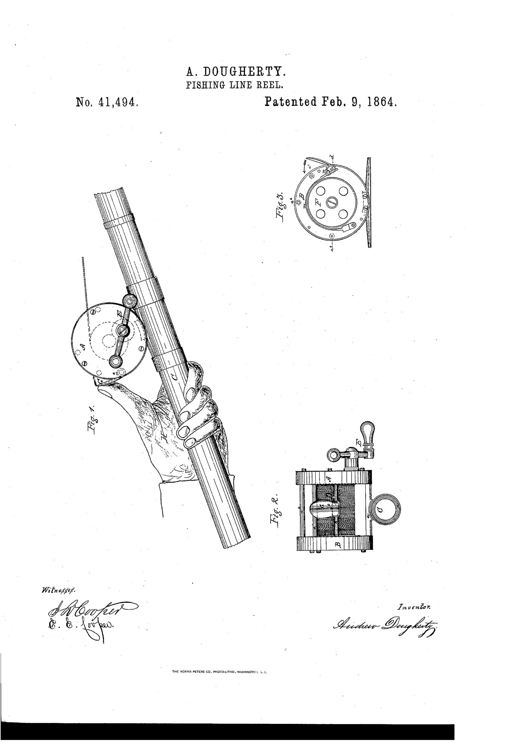
Angler's fishing reel with adjustable friction brake
↻ How it works
The reel has a double-headed frame with one head containing a winding mechanism operated by a crank and cog gearing, and the other head containing a friction brake. The brake consists of a spring-strap partially encircling a smooth-rimmed wheel on the spool arbor, controlled by a rock-shaft fitted with a thumb-plate positioned between the reel heads. The angler presses the thumb-plate with the hand holding the rod to apply braking pressure to the strap against the brake-wheel, controlling line unwinding without interfering with the winding crank. A set-screw and adjacent cross-bar limit the thumb-plate's movement and allow adjustment of brake tension to match line strength.
↻ What was claimed
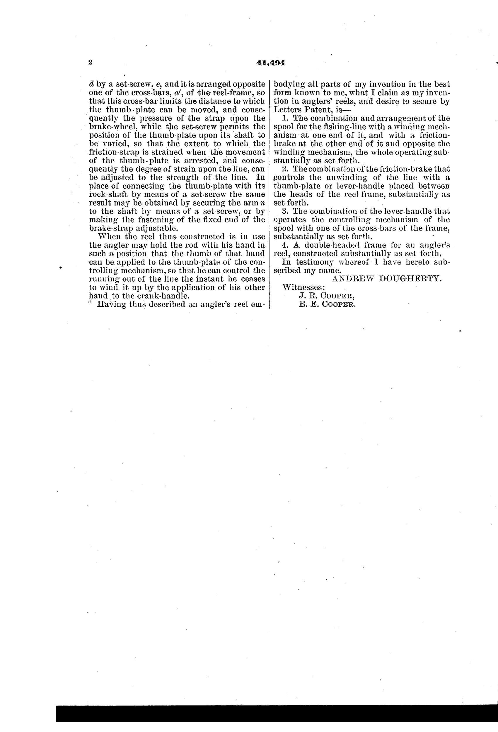
“The combination of the friction-brake that controls the unwinding of the line with a thumb-plate or lever-handle placed between the heads of the reel-frame, substantially as set forth.”
In plain English: The patent covers combining a friction brake for controlling line unwinding with a thumb-operated lever placed between the two reel heads.
↻ In the inventor’s words
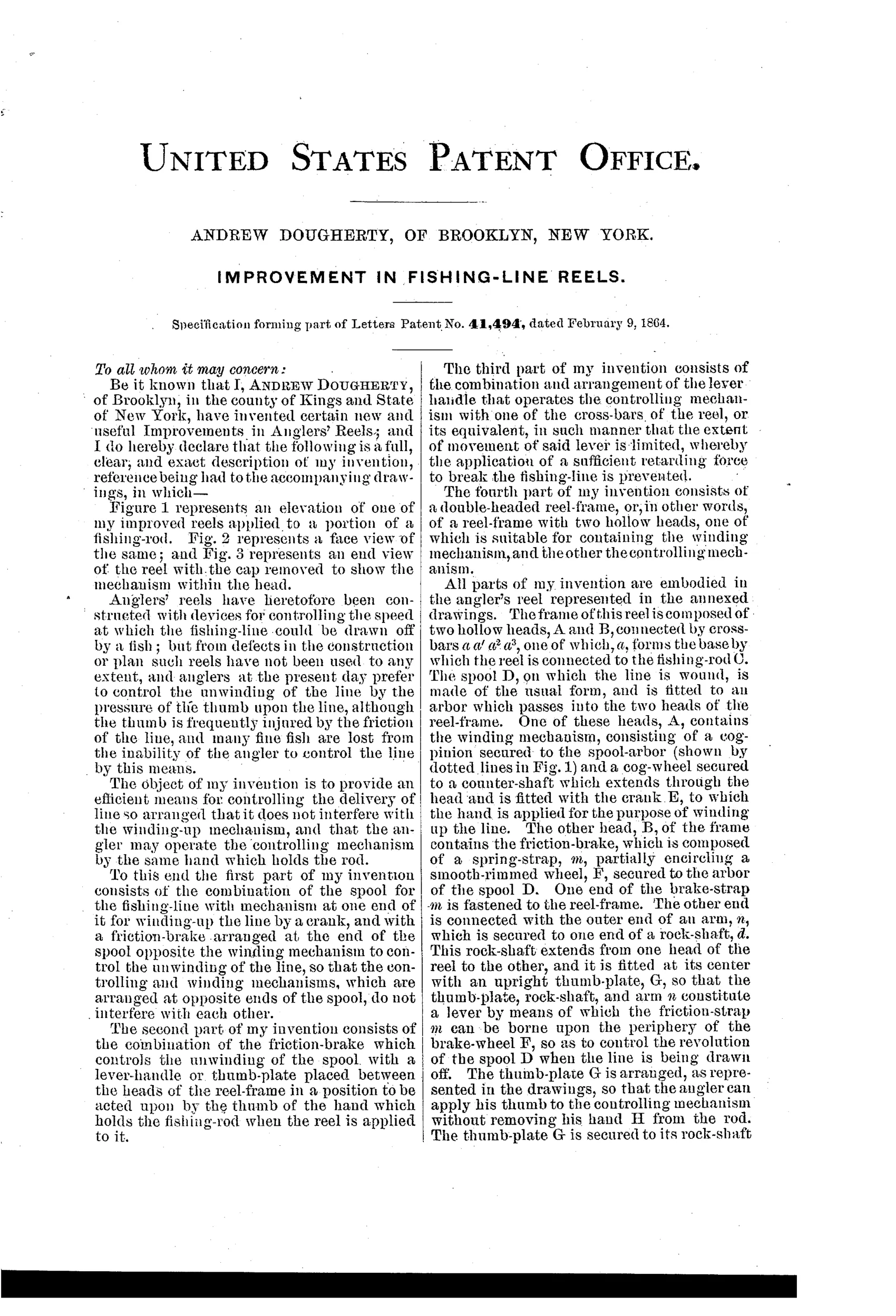
“The object of my invention is to provide an efficient means for controlling the delivery of line so arranged that it does not interfere with the winding-up mechanism, and that the angler may operate the controlling mechanism by the same hand which holds the rod.”— Andrew Dougherty, from the specification
Fate unknown
Dougherty was a documented Brooklyn reel maker, which raises the odds considerably, but a surviving reel bearing this thumb-plate brake would be needed to confirm this specific design reached production.
↻ Commentary
Most anglers in 1864 controlled a running fish the crude way: thumb pressed straight on the spool or line, with burned skin and snapped leaders as the cost of miscalculation. Dougherty's answer is a proper mechanical drag — a spring strap wrapped partway around a smooth brake wheel on the spool arbor, squeezed by a rock-shaft whose thumb-plate sits between the reel heads, right under the hand that holds the rod. Fig. 1 makes the ergonomic argument plainly: the drawing is of a hand gripping the rod, thumb falling naturally onto the plate. That figure is the whole sales pitch.
The detail a casual reader will miss is the set-screw and cross-bar limiting the thumb-plate's travel. That isn't decoration — it caps the maximum braking force so a panicked squeeze can't exceed the breaking strain of the line. That is adjustable drag in the modern sense, stated in 1864, some forty years before the trade made a fetish of controlling spool overrun.
Dougherty was no dreamer with a drawing board. He was a working Brooklyn reel maker in the years before Julius vom Hofe dominated that borough, and his reels turn up with maker stamps. Putting the brake on the head opposite the crank gearing, so drag and winding never fight each other, is exactly the kind of layout a man who built reels for a living would insist on. This patent is a genuine early landmark in drag design, whatever its commercial fate.
Commentary by Claude, The Fishing Reel Patent Archive’s resident enthusiast