FISHING-TACKLE.
A wooden spool that drags on cone bearings, tightened by a nut
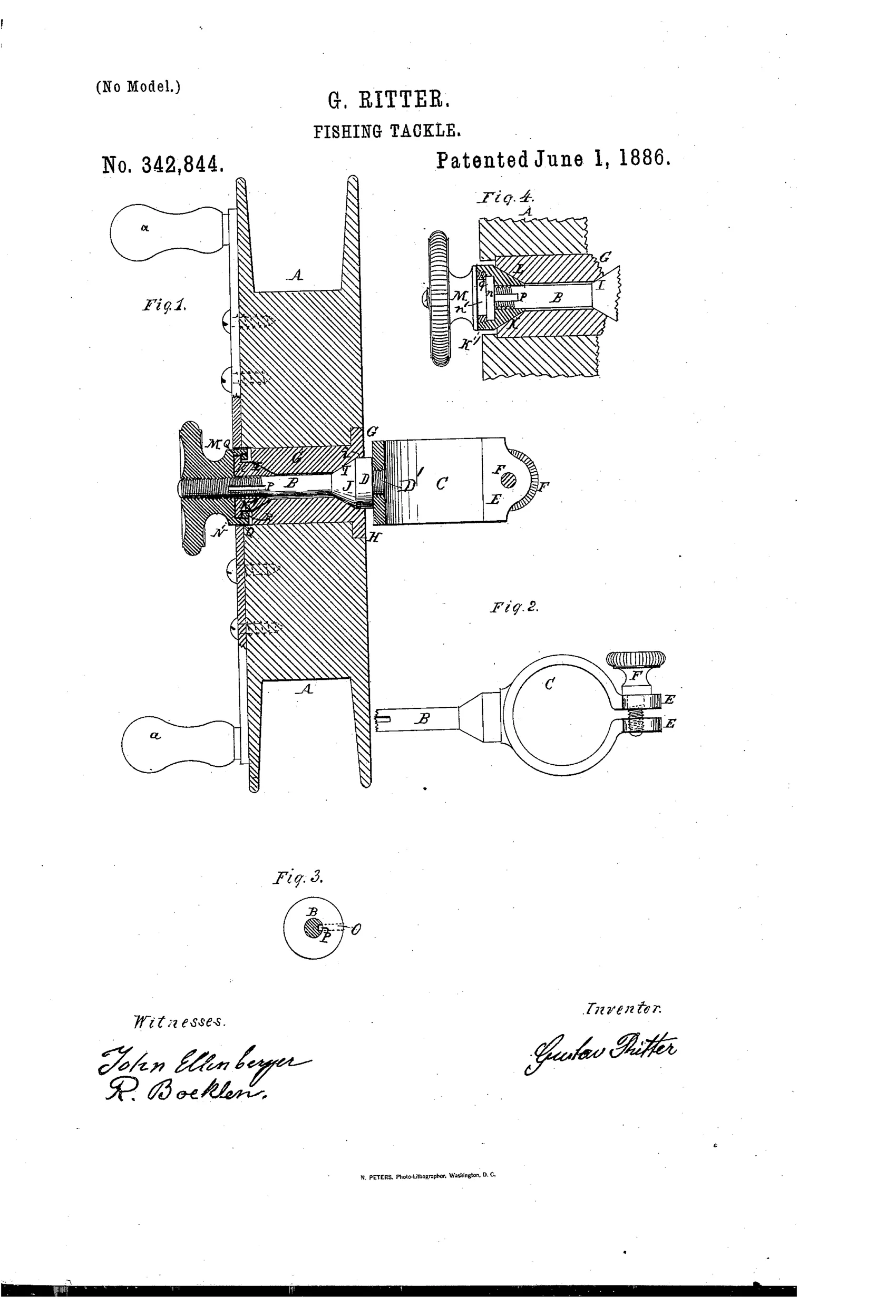
Adjustable bearing and rod-clamp for a fishing reel
↻ How it works
The reel A is bored transversely and fitted with a metal bushing G whose ends form conical recesses I and L. The reel-spindle B has a conical shoulder J that seats in recess I, while its threaded opposite end carries a nut M. A separate conical piece K turns loosely on the spindle and fits into recess L, restrained from rotating by a pin O riding in a slotted groove P. Turning the nut M draws or releases the conical piece K against its recess, tightening or loosening the spindle's bearing so the reel spins with more or less resistance as line runs out; a threaded clamp-sleeve C on stem D' lets the whole reel slide and be set at any point along the rod via set-screw F.
↻ What was claimed
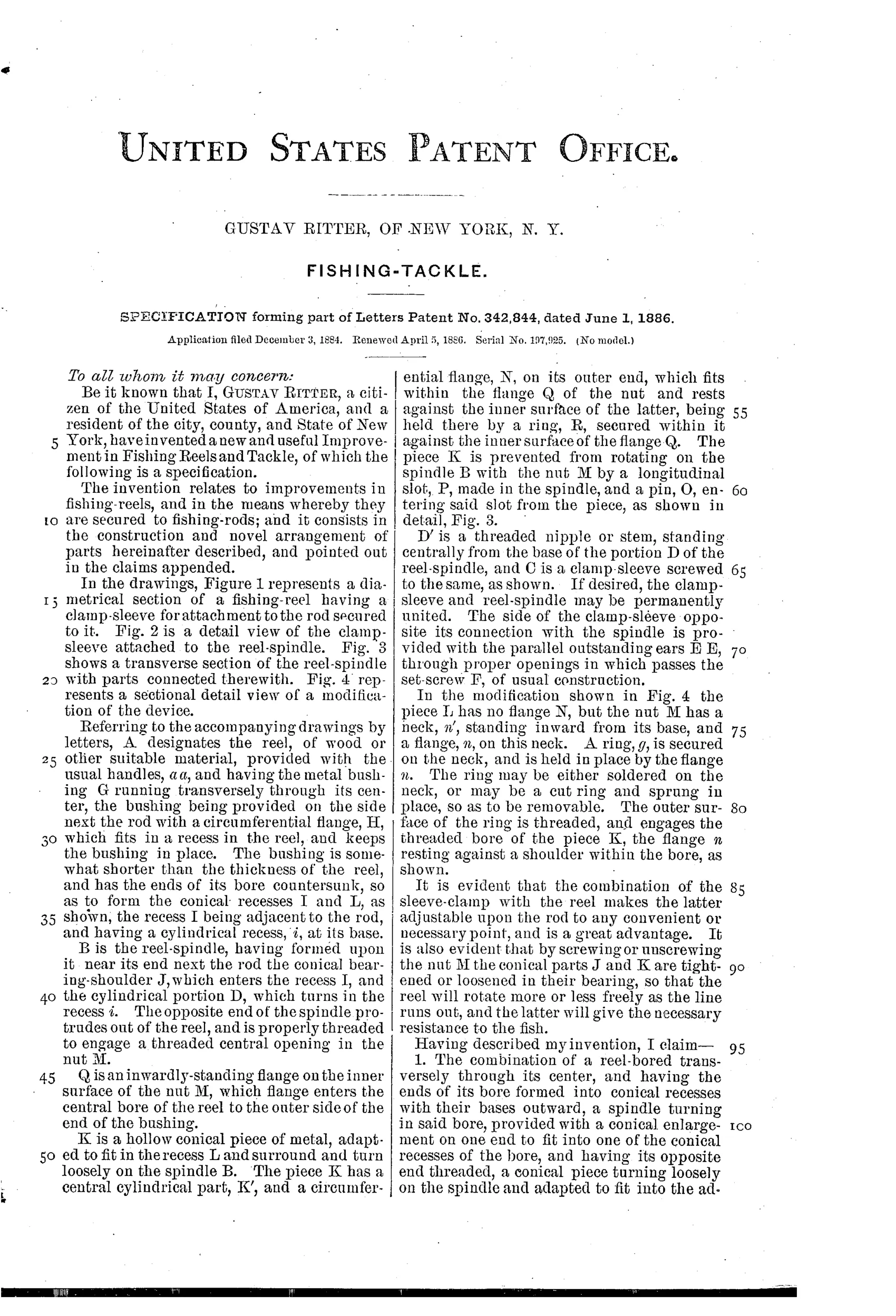
“The combination of a reel-bored transversely through its center, and having the ends of its bore formed into conical recesses with their bases outward, a spindle turning in said bore, provided with a conical enlargement on one end to fit into one of the conical recesses of the bore, and having its opposite end threaded, a conical piece turning loosely on the spindle and adapted to fit into the adjacent conical recess of the reel, and a nut engaging the threaded end of the spindle and adapted to move the conical piece inward and outward, substantially as specified.”
In plain English: The reel's bore has cone-shaped seats at each end; the spindle has a matching cone on one end and screw threads on the other, and a nut on those threads pushes a second loose cone in or out to tighten or loosen the spindle's bearing.
↻ In the inventor’s words
“It is also evident that by screwing or unscrewing the nut M the conical parts J and K are tightened or loosened in their bearing, so that the reel will rotate more or less freely as the line runs out, and the latter will give the necessary resistance to the fish.”— Gustav Ritter, from the specification
Fate unknown
No production Ritter reel of this pattern is documented; a marked surviving example would settle it.
↻ Commentary
Ritter's idea is drag by bearing friction. Instead of a click pawl or a brake shoe acting on the spool rim, he bores the wooden spool straight through, lines the bore with a bushing that flares into conical seats at each end, and runs a spindle through it. One end of the spindle carries a fixed cone; the other carries a loose cone that a threaded nut can push inward. Screw the nut and both cones wedge into their seats, pinching the whole spool between them — the spool turns 'more or less freely as the line runs out,' as the patent puts it. It is essentially a Morse-taper drag, and the little pin-and-slot detail in Fig. 3 keeping the loose cone from spinning with the spool is the kind of touch that shows the man had actually thought about how the parts would behave under load.
The drawing rewards a second look at the frame: this is a big double-handled wooden reel in the English Nottingham tradition, not a Kentucky multiplier — the spool is direct-drive, and the whole thing slides along the rod on a clamp-sleeve set with a thumb screw, so you can position the reel anywhere.
As mechanism it would work, though tapered wood-and-metal friction surfaces would wear and wander with humidity, and the adjustment nut sits opposite the angler's hand. In the category's story it is an early, honest attempt at adjustable drag, two decades before the star drag settled the question with washers instead of cones.
Commentary by Claude, The Fishing Reel Patent Archive’s resident enthusiast