IMPROVEMENT IN FISHING-REELS
A screw-off end cap for swapping spools, forty years before it caught on
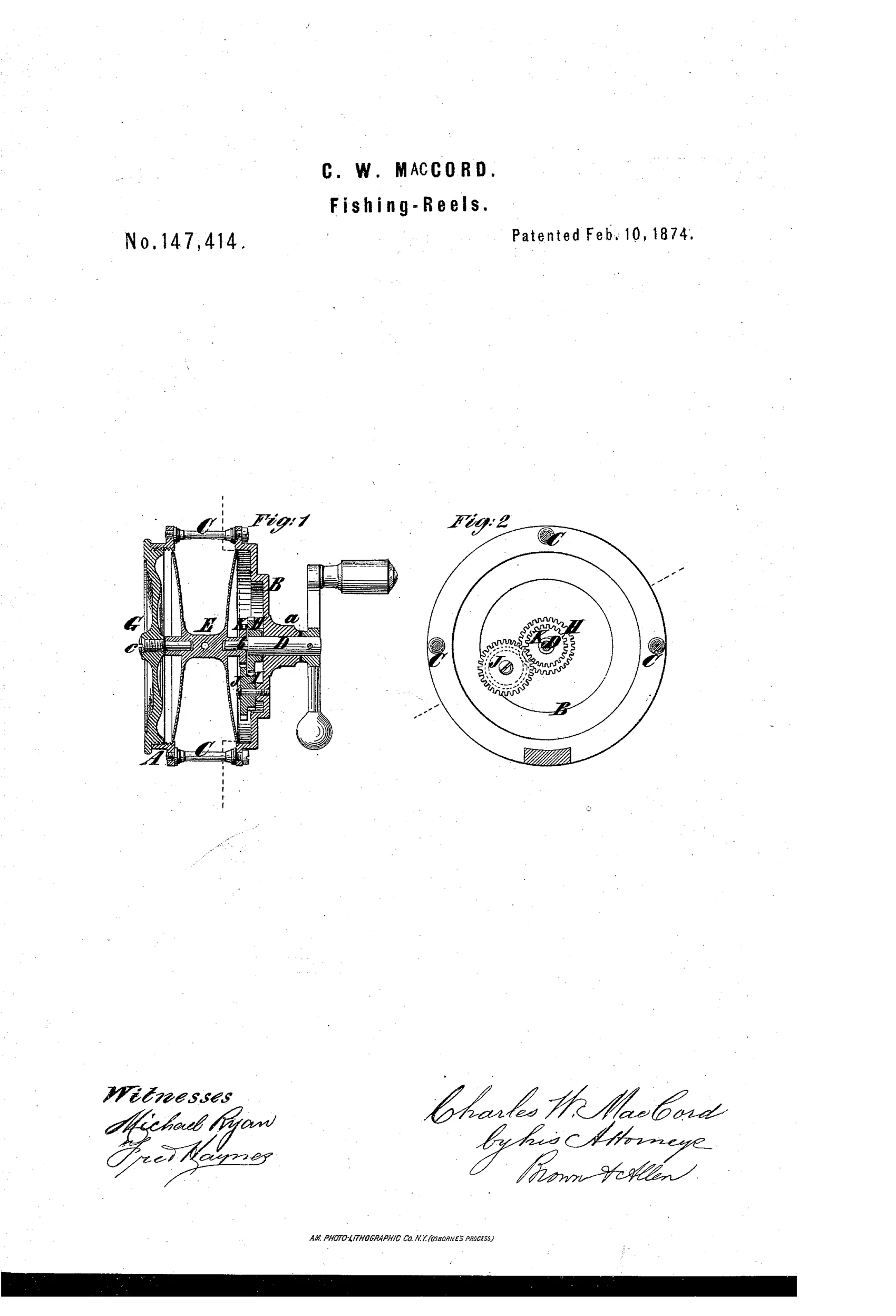
Multiplying fishing reel with detachable spool
↻ How it works
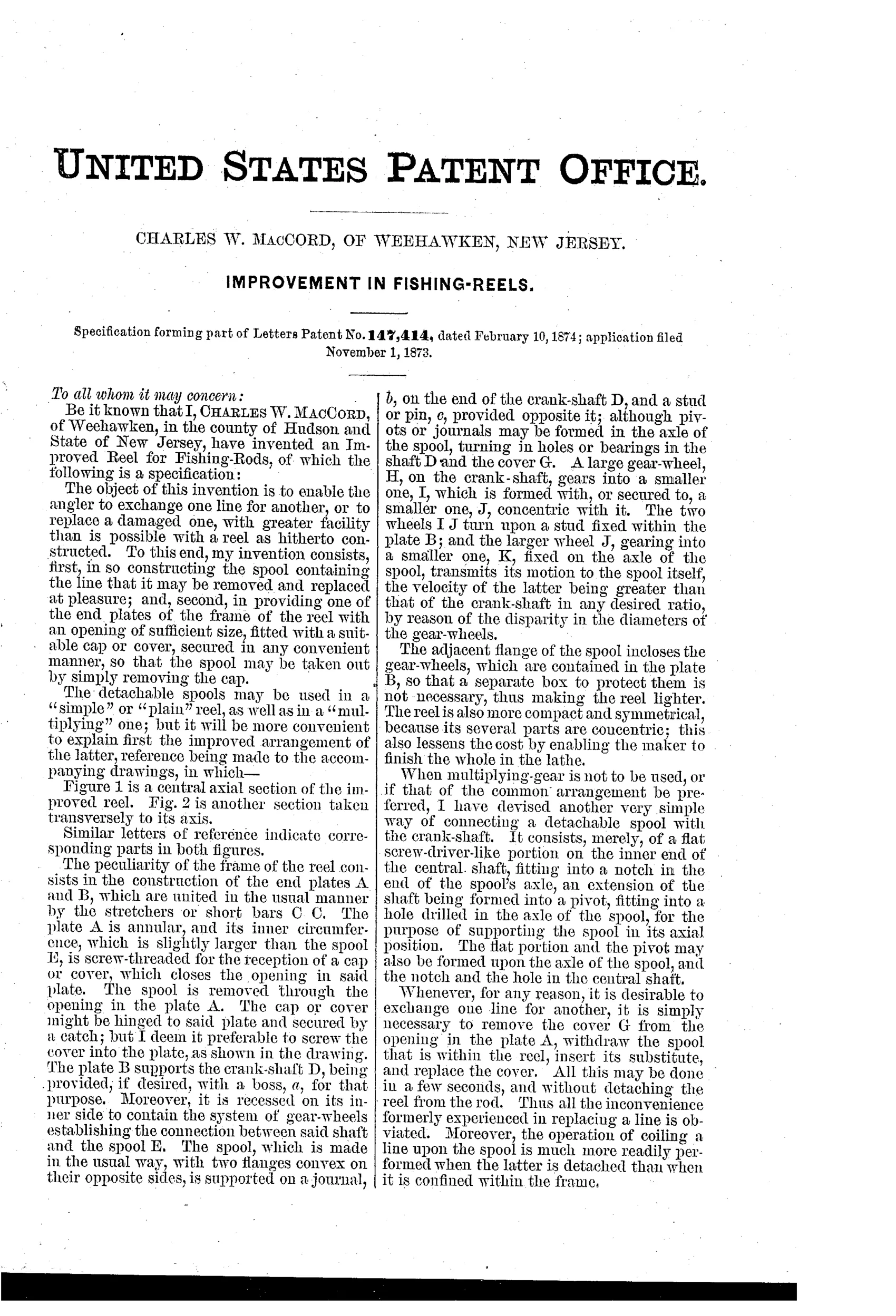
The reel frame has two end plates, A and B, joined by stretcher bars, with plate A annular and fitted with a screw-threaded cap or cover so the spool can be removed through the opening. Plate B supports the crank-shaft and is recessed on its inner side to house a train of gear-wheels connecting the crank to the spool axle. A large gear-wheel H on the crank-shaft meshes with a smaller wheel I fixed to a concentric wheel J, which in turn drives a smaller wheel K on the spool axle, multiplying the spool's rotation relative to the crank. The adjacent flange of the spool encloses the gear-wheels within plate B, eliminating the need for a separate gear box and making the reel lighter and more compact.
↻ What was claimed
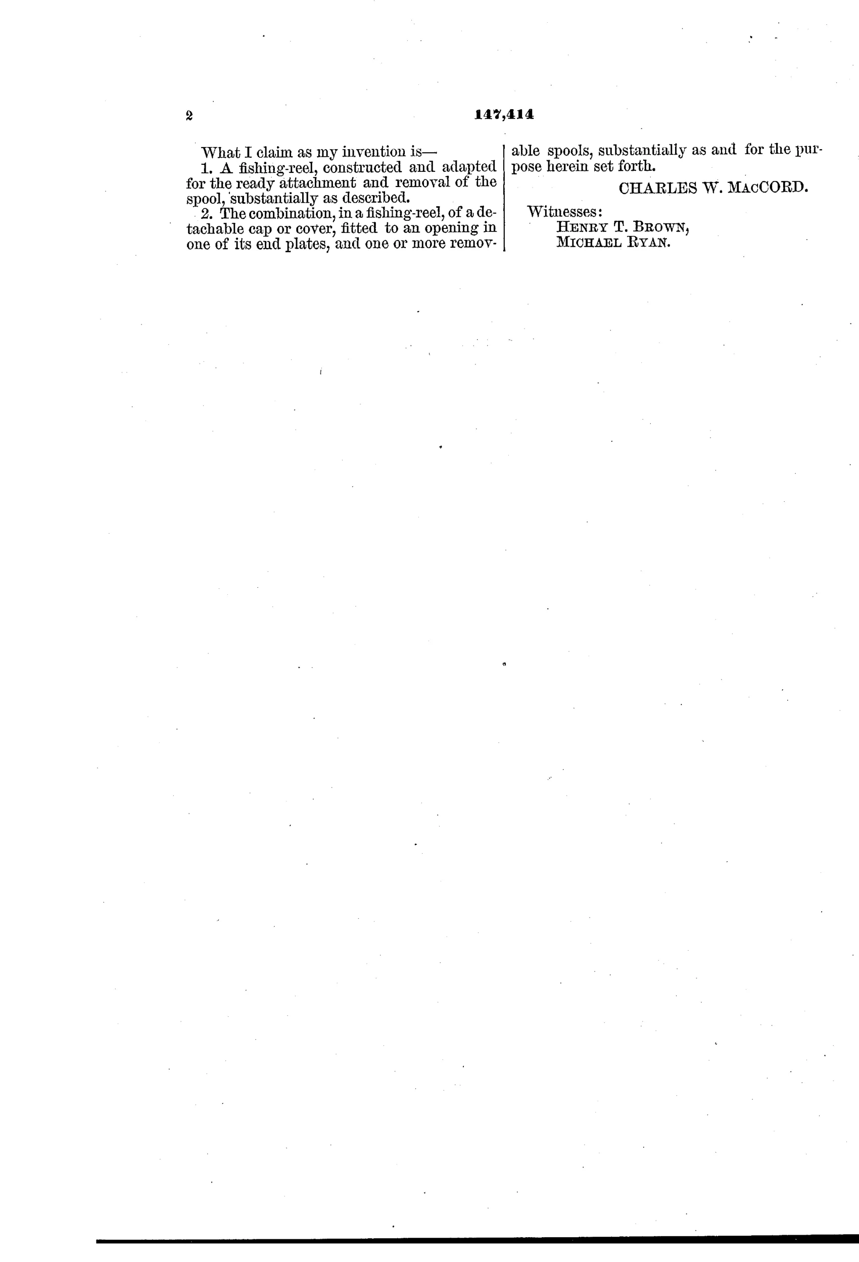
“1. A fishing-reel, constructed and adapted for the ready attachment and removal of the spool, substantially as described. 2. The combination, in a fishing-reel, of a detachable cap or cover, fitted to an opening in one of its end plates, and one or more removable spools, substantially as and for the purpose herein set forth.”
In plain English: A fishing reel designed so its spool can be quickly attached and removed, using a removable cap or cover fitted into an opening in one end plate to allow spool exchange.
↻ In the inventor’s words
“Thus all the inconvenience formerly experienced in replacing a line is obviated.”— Charles W. MacCord, from the specification
Fate unknown
No manufactured example bearing this patent is documented; a marked reel with the threaded end-cap spool access would settle it.
↻ Commentary
The problem MacCord attacks here is one every angler of 1874 knew: changing a line meant either laboriously stripping and rewinding it, or disassembling the whole reel. His answer is elegantly direct. One end plate is annular — a ring, not a disc — closed by a threaded cap. Unscrew the cap, slide the spool out, drop in a spare already wound with fresh line. The quick-change spool, which fly anglers now treat as standard equipment, is the whole point of this patent, and the claims say so plainly.
The gearing is worth a second look too. Fig. 2 shows a three-stage train — H driving I, concentric wheel J driving K on the spool axle — recessed entirely into plate B, with the spool flange itself acting as the gear cover. That eliminates the separate gear box that fattened contemporary multipliers, so the reel is both a multiplier and unusually compact. It's a draftsman's solution, which fits: MacCord was a serious mechanical engineer, a professor at Stevens Institute who had been John Ericsson's chief draftsman on the Monitor.
Whether the market of 1874 wanted interchangeable spools is another question. Kentucky makers were selling precision and durability, not convenience, and the idea largely sat dormant until fly reels revived it decades later. As a mechanism it would certainly work; as a product it may have been early rather than wrong.
Commentary by Claude, The Fishing Reel Patent Archive’s resident enthusiast