REEL FOR FISHING-RODS.
A free-spool clutch in 1856 — half a century before the idea caught on
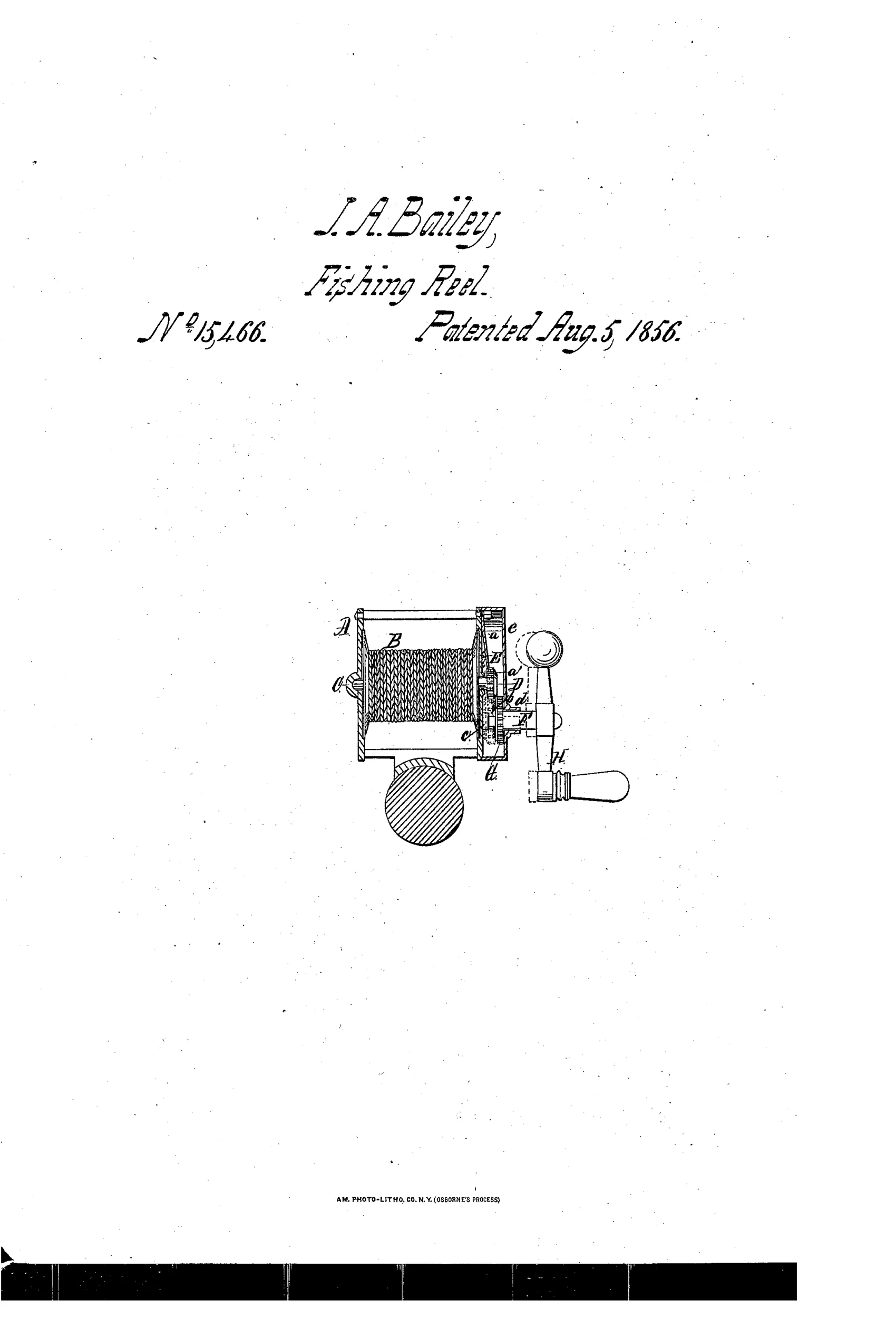
Fishing reel with disengaging gear mechanism
↻ How it works
The reel B turns on shaft C with a bevel-pinion D fixed to it, while a hollow crank-shaft F carrying a bevel-wheel G slides laterally in a socket on the frame's end plate. A spring E normally holds the wheel G out of gear with pinion D so the reel spins freely with minimal friction when casting. Pressing the crank H laterally pushes shaft F inward, engaging wheel G with pinion D so the crank can retrieve line by turning the reel through the gearing.
↻ What was claimed
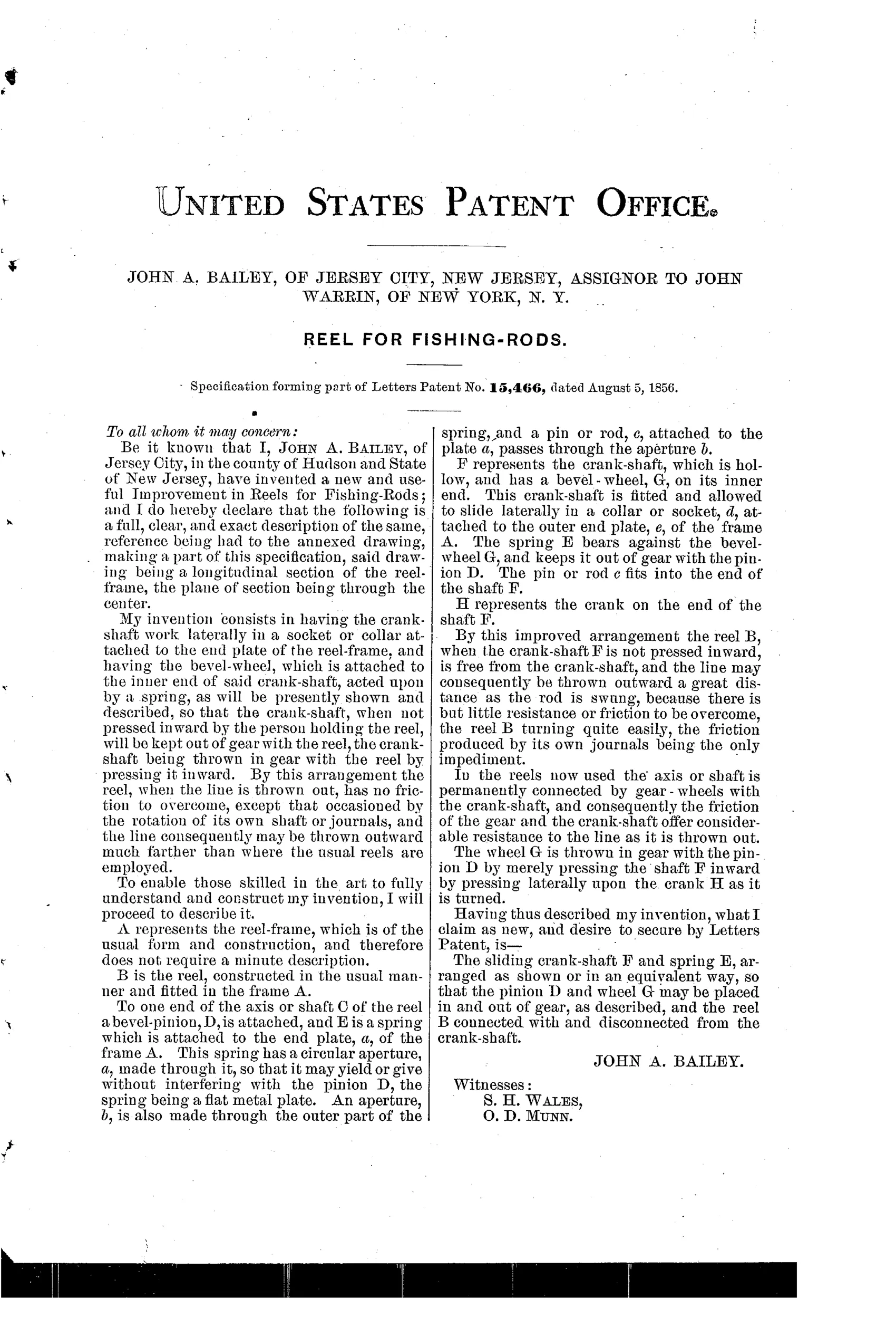
“The sliding crank-shaft F and spring E, arranged as shown or in an equivalent way, so that the pinion D and wheel G may be placed in and out of gear, as described, and the reel B connected with and disconnected from the crank-shaft.”
In plain English: The claim covers a crank-shaft that slides against a spring so its gear can be pushed in and out of mesh, letting the operator connect or disconnect the reel from the crank at will.
↻ In the inventor’s words
“By this arrangement the reel, when the line is thrown out, has no friction to overcome, except that occasioned by the rotation of its own shaft or journals, and the line consequently may be thrown outward much farther than where the usual reels are employed.”— John A. Bailey, from the specification
Fate unknown
The assignment to tackle dealer John Warrin hints at production, but I know of no documented surviving example; a marked specimen with this sliding crank-shaft would settle it.
↻ Commentary
Here is a genuinely startling piece of foresight. Bailey's claim is a sliding crank-shaft whose bevel-wheel is held out of mesh by a spring, so the spool spins on nothing but its own journals during the cast. That is a free-spool mechanism, described in plain terms, decades before the anti-backlash and free-spool obsessions of 1900-1920. His stated reason — the line "may be thrown outward much farther than where the usual reels are employed" — shows he understood exactly why multiplying gear trains hurt casting: the angler is dragging the whole gearing and crank around with the spool.
The drawing rewards a close look. The crank-shaft F is hollow and slides laterally in its socket; you press the handle inward against spring E to bring wheel G into mesh with pinion D on the spool shaft, then wind. Release, and the spring throws it out of gear again. It is essentially a dog clutch made of the gears themselves — crude, since bevel teeth engaged under a spring's shove will clash and wear, and you must hold sideways pressure the entire time you retrieve. Later free-spool designs used a proper throw-out lever for good reason.
Still, the Kentucky makers were then perfecting jeweled multipliers with the gears always engaged; nobody was asking Bailey's question yet. The assignment to John Warrin, a New York tackle dealer, suggests real commercial intent even if the execution needed another generation of refinement. A dead end in form, prophetic in purpose.
Commentary by Claude, The Fishing Reel Patent Archive’s resident enthusiast