SPEED-REGULATOR.
A machinery governor, not a reel — but the ancestor of centrifugal anti-backlash
Automatic centrifugal friction-clutch speed governor for machinery
↻ How it works
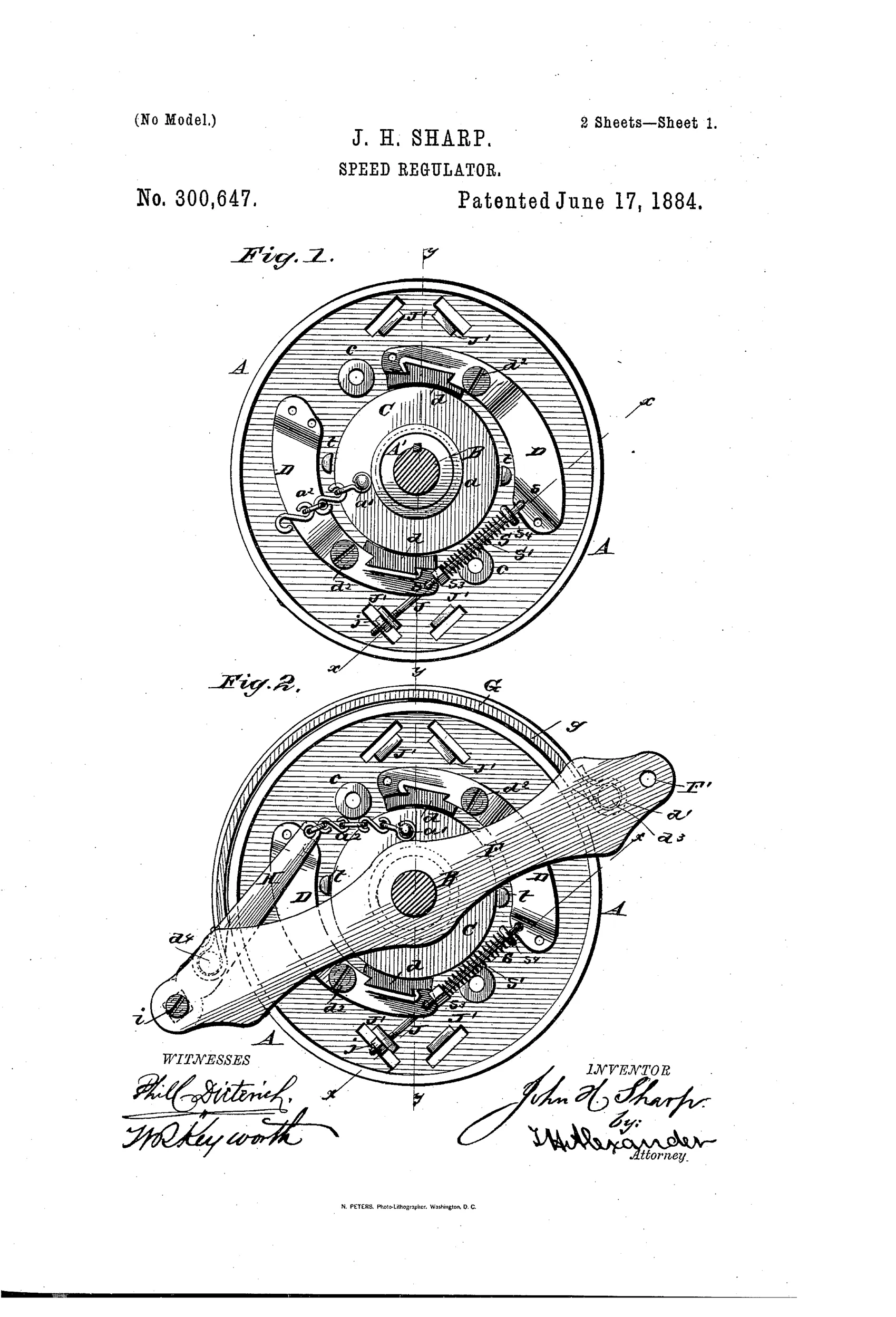
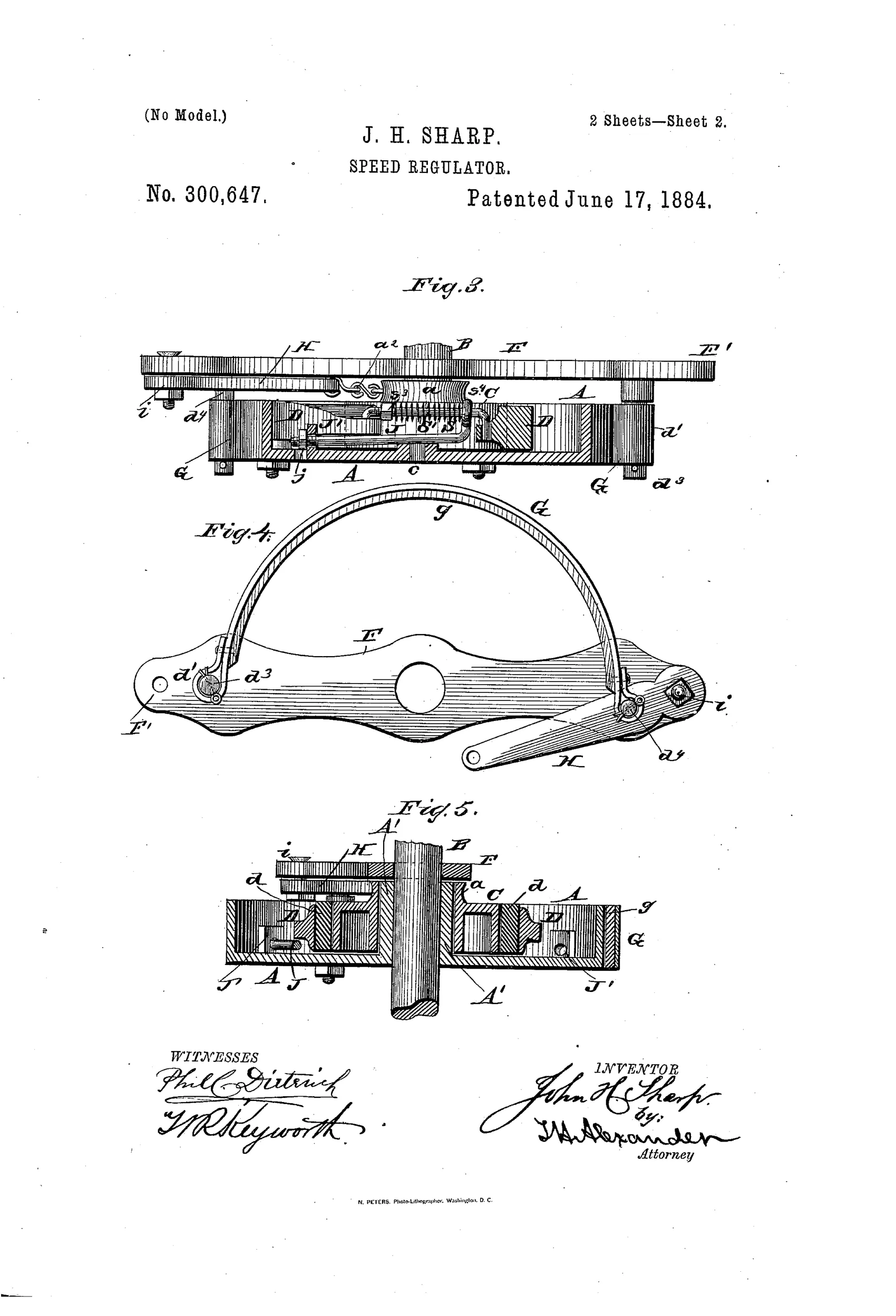
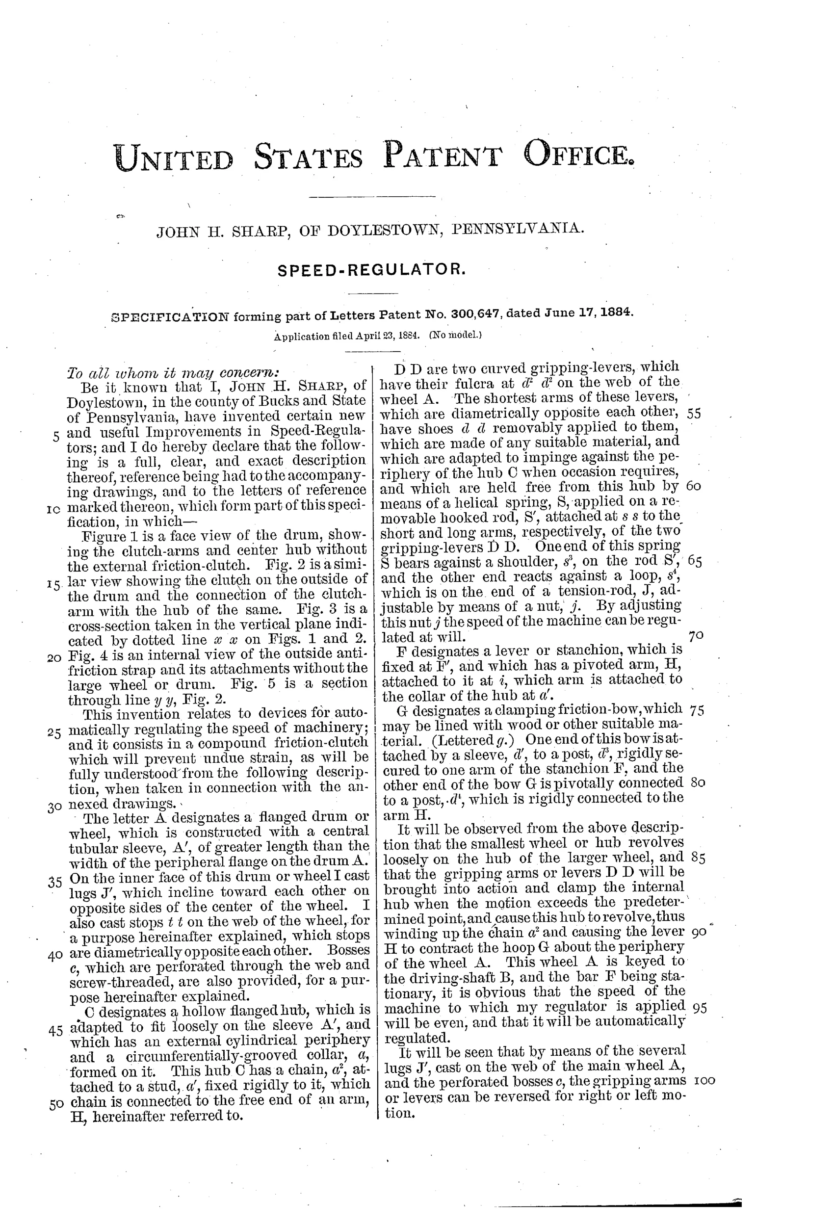
A flanged wheel keyed to the driving shaft carries an internal hub that revolves loosely on a sleeve extending from the wheel. Curved gripping levers pivoted on the wheel's web are held clear of the hub by a helical spring whose tension is set with an adjustable nut. When rotational speed exceeds the preset point, the levers overcome spring tension and clamp the hub, causing it to revolve and wind up a chain connected to a pivoted arm. This arm, fixed to a stationary stanchion, tightens an external friction bow (hoop) around the periphery of the main wheel, applying drag and evening out the machine's speed automatically.
↻ What was claimed
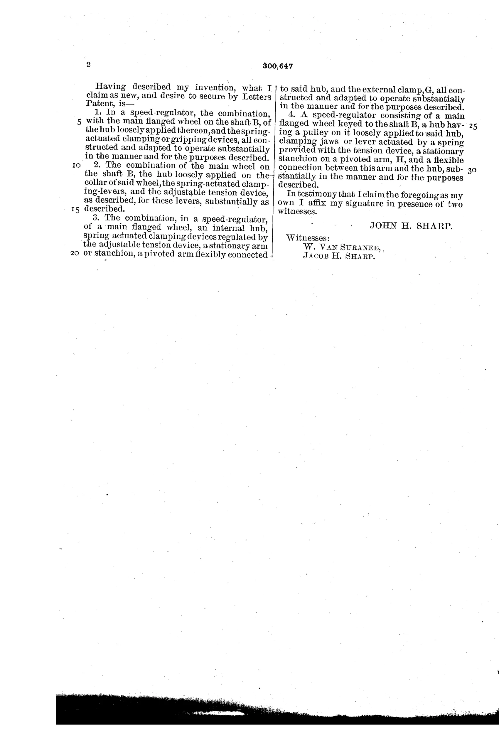
“A speed-regulator consisting of a main flanged wheel keyed to the shaft B, a hub having a pulley on it loosely applied to said hub, clamping jaws or lever actuated by a spring provided with the tension device, a stationary stanchion on a pivoted arm, H, and a flexible connection between this arm and the hub, substantially in the manner and for the purposes described.”
In plain English: The regulator combines a shaft-mounted wheel, a loose hub with clamping jaws sprung to a set tension, and a pivoted stanchion arm linked to the hub by a chain, so that excess speed triggers clamping which pulls the arm and brakes the wheel.
↻ In the inventor’s words
“It will be observed from the above description that the smallest wheel or hub revolves loosely on the hub of the larger wheel, and that the gripping arms or levers D D will be brought into action and clamp the internal hub when the motion exceeds the predetermined point, and cause this hub to revolve, thus winding up the chain a2 and causing the lever H to contract the hoop G about the periphery of the wheel A.”— John H. Sharp, from the specification
Fate unknown
No production record of Sharp's governor is documented, and as general machinery rather than a reel it falls outside the makers we can trace; a surviving marked example would settle it.
↻ Commentary
Let's be straight: this is not a fishing reel. Sharp's patent is a speed regulator for shop machinery — a flanged wheel keyed to a driving shaft, with curved gripping levers held off an internal hub by an adjustable spring. Run the shaft too fast and centrifugal force swings the levers into the hub, the hub winds up a chain, and the chain pulls a pivoted arm that cinches a friction hoop around the wheel's rim. Speed drops, levers release, brake eases. It is a self-regulating feedback loop, done entirely in cast iron and spring wire.
So why look at it here? Because the principle — spinning mass overcoming spring tension to apply friction proportional to speed — is exactly the logic that reel designers would chase twenty-five years later in the great anti-backlash scramble of 1900-1920. A casting reel's spool overrunning the line is a speed-governing problem in miniature, and centrifugal brake blocks inside spool flanges became one of the standard answers. Sharp's drawing, with its levers pivoted on the web and its tension nut for setting the trip point, reads like a rough draft of that idea at industrial scale.
The self-tightening chain-and-hoop arrangement is clever but fussy; the two-stage action (clutch grabs, then brake tightens) adds lag and wear points that a direct centrifugal shoe avoids. As a governor it would work, roughly. As a page in this collection, it earns its place as prehistory.
Commentary by Claude, The Fishing Reel Patent Archive’s resident enthusiast